3D Intersection of Line and Point Cloud
Operator Function
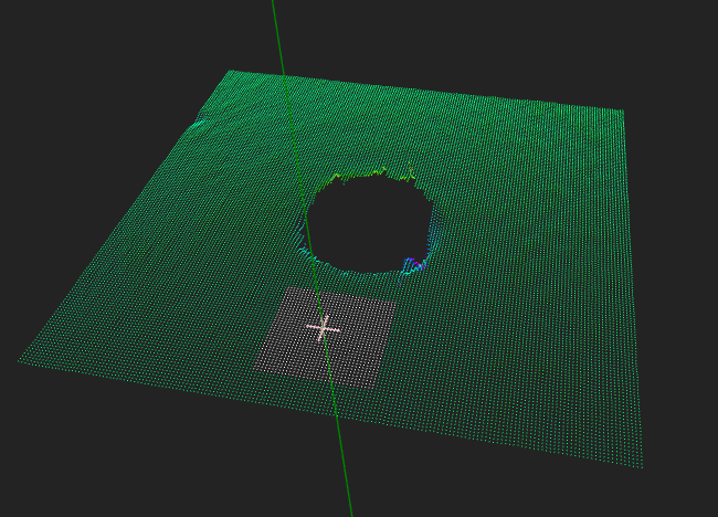
Input a point cloud and a line, set the point cloud reconstruction parameters, and compute the intersection point of the point cloud and the 3D line.
Parameters
Input Parameters
| Parameter | Range | Default | Description | Diagram |
|---|---|---|---|---|
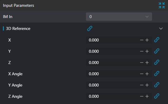
| Input Image | 0-8 | 0 | IM index of the input image | |
| 3D Datum | You can select Datum by binding | 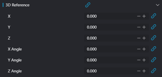 | ||
| X | X coordinate value of the 3D datum parameter; you can set X by binding | |||
| Y | Y coordinate value of the 3D datum parameter; you can set Y by binding | |||
| Z | Z coordinate value of the 3D datum parameter; you can set Z by binding | |||
| X-Axis Angle | -10000000000.000-10000000000.000 | X-axis angle value of the 3D datum parameter; you can set X-Axis Angle by binding | ||
| Y-Axis Angle | -10000000000.000-10000000000.000 | Y-axis angle value of the 3D datum parameter; you can set Y-Axis Angle by binding | ||
| Z-Axis Angle | -10000000000.000-10000000000.000 | Z-axis angle value of the 3D datum parameter; you can set Z-Axis Angle by binding |
Calculation Parameters
| Parameter | Range | Default | Description | Diagram |
|---|---|---|---|---|
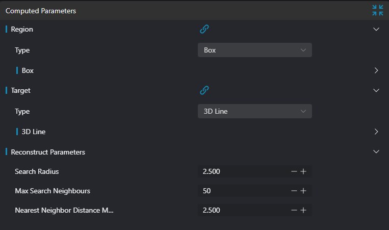
| Region | 2D Window / 2D Circular Window / 2D Polygon Window / Box / Cylinder Box / Rotated Box / Point Set (binding only) | Box | Manually select a suitable ROI regionYou can select an existing ROI region by binding | |
| Target | 3D Line | 3D Line | Input 3D line parameters | |
| Search Radius | 0-200 | 2.500 | Set the sphere radius used to determine the k-nearest neighborhood This value may need adjustment according to the density and distribution of the point cloud. For example, for sparser point clouds, a larger search radius may be needed | 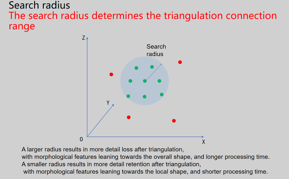 |
| Number of Neighbors | 1-100 | 50 | Set the maximum number of neighbors for normal estimation of the weld point cloud A larger value may improve the robustness of normal estimation, especially when the point cloud is sparse or irregular. However, an excessively large value may also increase the computational burden and introduce unnecessary noise. A smaller value may improve computational efficiency but, in some cases, lead to inaccurate normal estimation | 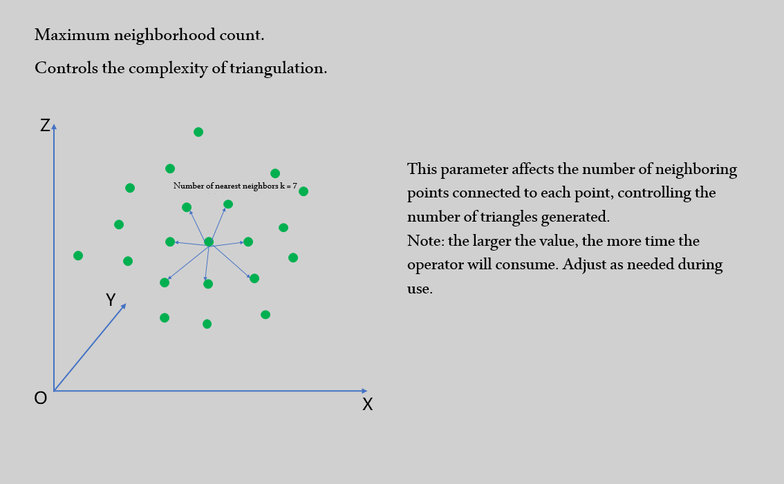 |
| Neighbor Distance Multiplier | 0-50 | 2.500 | Dynamically adjust the maximum search distance for each sample point; the larger this value, the larger the maximum search distance for the final sample points. When set to a larger value, the search radius increases, meaning the algorithm considers more neighboring points to construct triangles, which may be beneficial in sparser regions of the point cloud. However, if set too large, it may cause over-connection and produce inaccurate triangles. When set to a smaller value, the search radius decreases and the algorithm considers fewer neighboring points. This may be beneficial in denser regions of the point cloud or when finer reconstruction is needed. However, if set too small, it may miss some points that should be connected, resulting in an incomplete triangular mesh. | 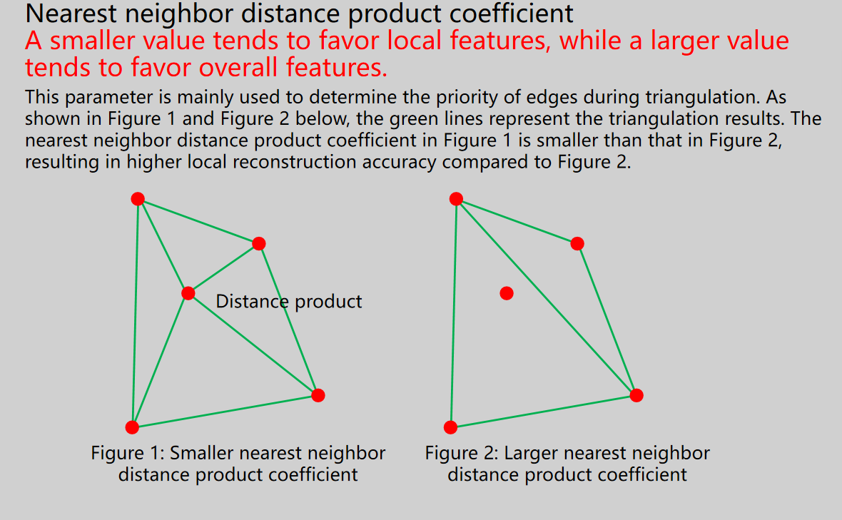 |
Result Display
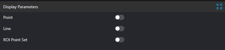
| Parameter | Range | Default | Description | Diagram |
|---|---|---|---|---|
| Point | true/false | false | Intersection point; when enabled, displayed in the image | |
| Line | true/false | false | The input line; when enabled, displayed in the image | |
| ROI Point Set | true/false | false | Only effective when Use Region Parameter is checked; the region point set selected by the ROI; when enabled, displayed in the image |
Output Parameters
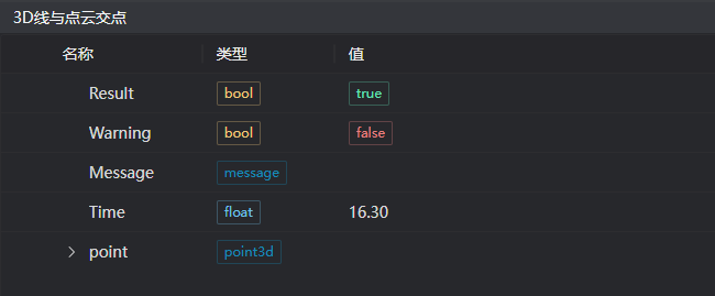
| Name | Type | Range | Description |
|---|---|---|---|
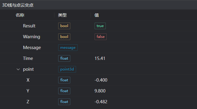
| Result | bool | true/false | true for success false for failure |
| Warning | bool | true/false | true indicates a warning false indicates none |
| Message | string | Output success, error, or warning message; empty if no error or warning | |
| Time | float | Operator execution time, unit: ms | |
| point | point3d | Intersection point coordinates | |
Note: When the input is an array, all surface areas measured from the arrays will form an array. |
Tip
For more details on parameter types, please refer to Type Definition
Troubleshooting
| No. | Exception Message | Corresponding Parameter | Solution |
|---|---|---|---|
| 1 | The input region type is {0}, an invalid region type | Region Type | The region input type is one of 2D Window / 2D Circular Window / 2D Polygon Window / Box / Cylinder Box / Rotated Box / Point Set |
| 2 | The region is empty | 1. Check each region for any empty selection 2. Check each point set for any empty point set | |
| 3 | Input point cloud is empty | Confirm whether the IM contains valid points. If no valid point exists, load the point cloud or switch to an IM with valid points | |
| 4 | The number of polygon vertices is less than 3, cannot form a polygon | Add 2D polygon window vertices so that the number of vertices is at least three | |
| 5 | The point cloud patch reconstructed from the input parameters is empty | Modify the point cloud reconstruction parameters: increase the search radius and the neighbor distance multiplier | |
| 6 | The currently reconstructed point cloud has no intersection with the line | The point cloud and the line do not intersect, or the reconstruction result is inaccurate, causing no intersection between the line and the reconstructed point cloud | |
| 7 | The type of the input line is {0}, an invalid line type | Line Type | The input line type is "3D Line" |
Examples
Engineering Setup
Select the
Load Point Cloudtool to load the 3D point cloud to be processed into IM0;Select the
3D Intersection of Line and Point Cloudtool.
Tool Usage
Select the input image to be operated on; the image index must match the IM index of the image in the project.
Either disable the use-region parameter, or enable the region and select the region type as Box, then move the box to the position to be measured so that it encloses the point cloud to be measured.
Usage Tips
1. Drag or scale the box via the ROI controller on the image window;
2. Directly modify the start or end coordinates of the box in the calculation parameters to adjust the box position and size
Set the parameters.
Check the items to be displayed in the Result Display panel.
Click
Testto check whether the image window and parameters meet expectations.After confirming there are no problems, click
Save, then run the operator in the run list to view the running result in the corresponding IM.