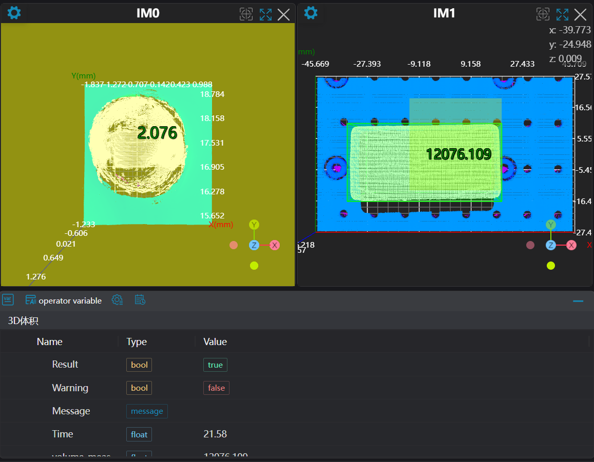
3D Volume
Operator Function
Calculate the volume of the point cloud in a given region. Provides three volume measurement algorithms: calculating volume based on bounding box, contour integration, and slice integration.
Parameter Introduction
Input Parameters

| Parameter | Range | Default Value | Description | Illustration |
|---|---|---|---|---|
| Input Image | 0-8 | 0 | IM number for image input | |
Calculation Parameters
| Parameter | Range | Default Value | Description | Image |
|---|---|---|---|---|
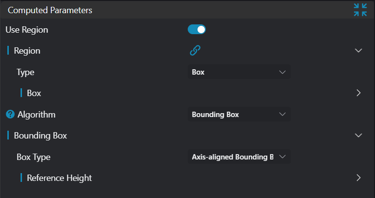
| Use Region Parameters | true/false | false | If enabled, use Region as input; if disabled, use Input Image as input | |
| Region | Set the volume calculation region | |||
| Algorithm | Bounding Box/Contour Integration/Slice Integration | Bounding Box | Bounding Box: Calculate volume based on bounding boxContour Integration: Calculate volume by integrating the Z-direction height of each point based on the input point cloud contour. Note: This algorithm requires input of ordered point cloudSlice Integration: Calculate volume based on slice integration. (Contour Integration algorithm requires input of ordered point cloud) | 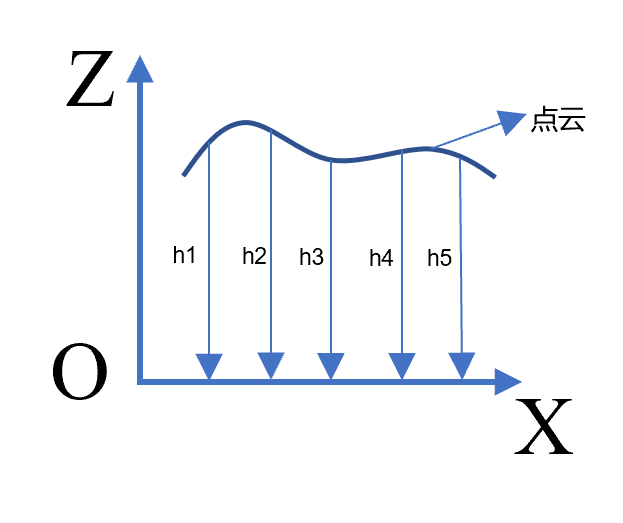 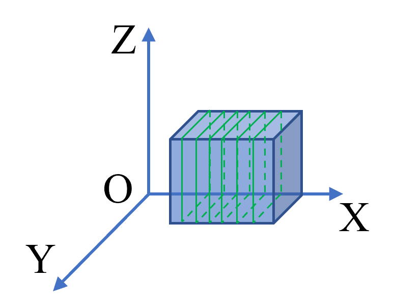 |
| Bounding Box Type | Axis-Aligned Bounding Box/Oriented Bounding Box | Axis-Aligned Bounding Box | Axis-Aligned Bounding Box: The boundaries of the bounding box are parallel or perpendicular to any coordinate axis. Its parameters are minimum x, y, z coordinates and maximum x, y, z coordinates. For rotating objects, the fit is not tight, and there is more redundant space.Oriented Bounding Box: Can better fit the object. Parameters are center point coordinates, length, width, height, rotation Euler angles. | 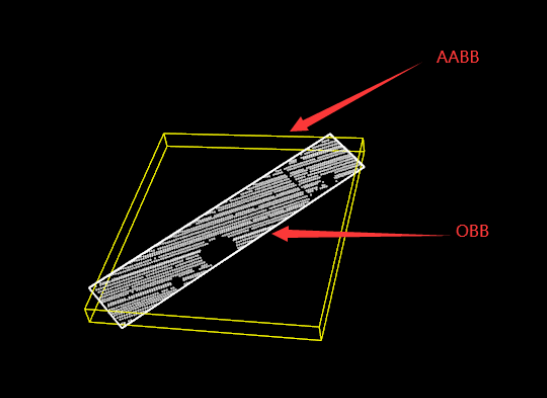 |
| Reference Height | 0.000 | When Algorithm is set to Bounding Box, the height of the reference plane needs to be set | 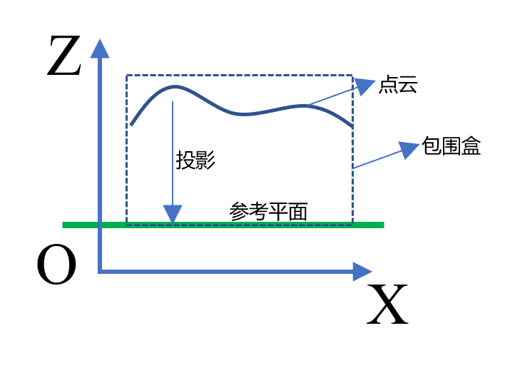 | |
| Number of Slice Contours | 1000 | Required when Algorithm is set to Slice Integration: The number of contours to be sliced. More contours result in more accurate volume calculation, but increasing the number will increase computational load. Adjust accordingly during use. | ||
| Slice Direction | X/Y/Z | X | Required when Algorithm is set to Slice Integration: The normal direction of the cutting plane. Currently can be set to X, Y, and Z. The slice direction is the X direction. |
Result Display
| Parameter | Range | Default Value | Description | Illustration |
|---|---|---|---|---|
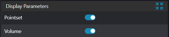
| Box | true/false | false | Bounding box of the object. If enabled, display in the image | |
| Point Set | true/false | false | Target region point set. If enabled, display in the image |
Output Parameters
| Name | Type | Range | Description |
|---|---|---|---|
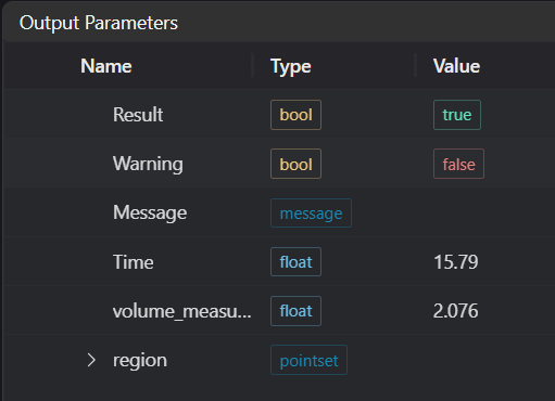
| Result | bool | true/false | true for success false for failure |
| Warning | bool | true/false | true indicates a warning false indicates no warning |
| Message | string | Output success, error, or warning messages. Empty if no error or warning. | |
| Time | float | Operator execution time, unit: ms | |
| volume_measurement | float | Volume measurement value | |
| region | pointset | Target region point set |
Exception Troubleshooting
View the error code list for general error information and solutions.
| No. | Exception Information | Corresponding Parameter | Solution |
|---|---|---|---|
| 1 | Input value is {0}, invalid region type | Region Type | Only window2d, box, pointset supported |
| 2 | Region is empty | 1. Check if input point cloud is empty 2. Check if ROI region selects point cloud 3. Check if bound pointset is empty | |
| 3 | Only ordered point cloud input supported in this mode | Contour integration mode only supports ordered point cloud | |
| 4 | Contour integration calculation failed | Check if input point cloud is empty | |
| 5 | Input x resolution is {0}, y resolution is {1}, invalid x or y direction resolution | x resolution, y resolution | Only x resolution>0, y resolution>0 supported |
| 6 | Input value is {0}, invalid slice direction | Slice Direction | Only slice directions X, Y supported |
| 7 | Please increase x resolution or y resolution value | x resolution or y resolution >= point cloud point spacing | |
| 8 | Volume calculation failed | Check if number of slice contours is set greater than 0 |
Example Introduction
Engineering Design
- Select two
Load 3D Point Cloudtools to load two point clouds for volume calculation. - Select the
Parallel Call Programtool to useSlice Volume AlgorithmandBounding Box Algorithmrespectively to calculate the volumes of the two point clouds. - In the
Slice Volume Algorithmprogram, select3D Region Operation,3D Plane Fitting, and one3D Volumetool. The3D Region Operationand3D Plane Fittingtools are used to adjust the point cloud to the zero plane, and the3D Volumetool uses theSlice Integrationalgorithm to calculate the volume. - In the
Bounding Box Algorithmprogram, select3D Region Operation,3D Plane Fitting, and two3D Volumetools. The3D Region Operationand3D Plane Fittingtools are used to adjust the point cloud to the zero plane, and the two3D Volumetools are used to calculateAxis-Aligned Bounding Boxvolume andOriented Bounding Boxvolume respectively.
Tool Usage
Set the IM number of the input image.
Set the parameters.
Click
Testto view the calibration matrix.If there are no issues, click
Save. Run the operator in the run list, and then view the running results.