3D Coplanarity
Operator Function
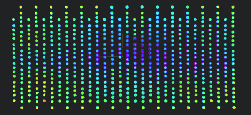
Perform coplanarity measurement on input point cloud images, such as BGA solder balls. The output coplanarity is the standard deviation of all point heights.
Parameter Introduction
Input Parameters

| Parameter | Range | Default Value | Description | Illustration |
|---|---|---|---|---|
| Input Image | 0-8 | 0 | IM number for image input | |
Calculation Parameters
| Parameter | Range | Default Value | Description | Illustration |
|---|---|---|---|---|
| Region | Can manually select the region for coplanarity calculationCan bind to select existing ROI region | |||
| 3D Blob Parameters | See 3D Blob Parameters | |||
| Output Image | 0-8 | 0 | IM number for image output |
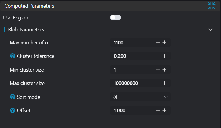
3D Blob Parameters
3D blob extraction is performed before coplanarity calculation. These parameters help with correct blob acquisition.
| Parameter | Range | Default Value | Description | Illustration |
|---|---|---|---|---|
| Maximum Output Blob Count | 1 | Maximum number of blobs that can be output | ||
| Maximum Distance Threshold | 0.500 | Distance threshold to distinguish between two different blobs. If the distance between adjacent blobs is small, try reducing this value. | 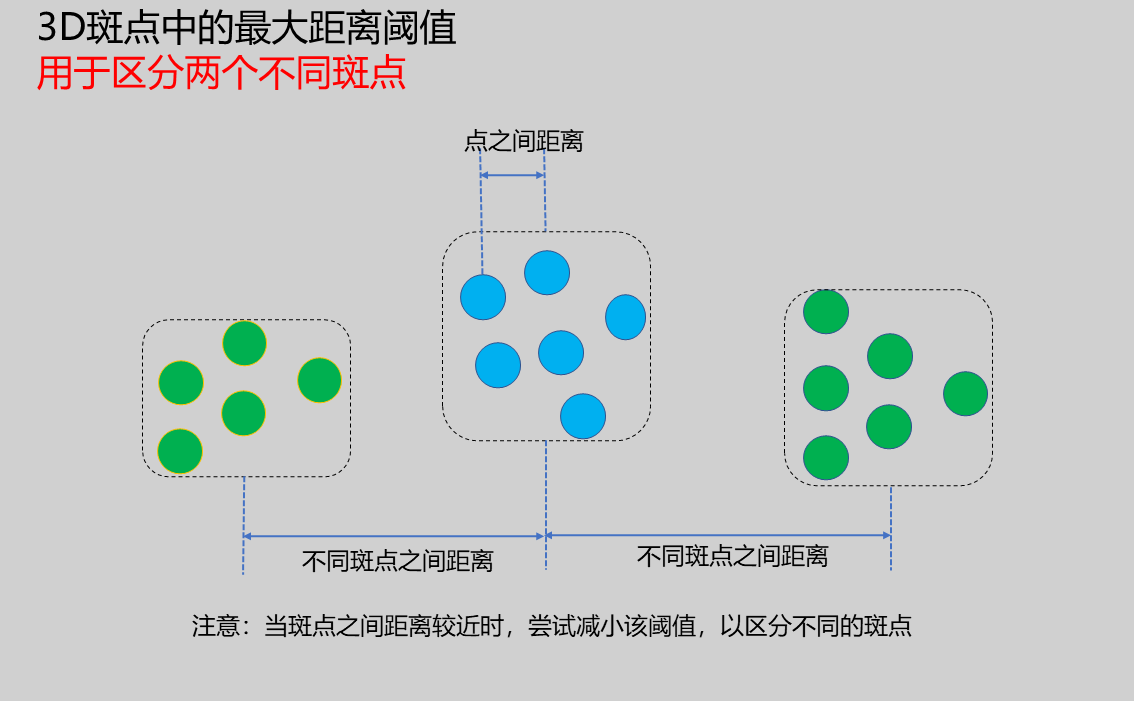 | |
| Minimum Points Per Blob | 1 | Minimum number of points that each blob must contain, which can filter blobs. | ||
| Maximum Points Per Blob | 100000000 | Maximum number of points that each blob can contain, which can filter blobs. | ||
| Sorting Method | +X/-X/+Y/-Y/+Z/-Z | -X | Sort the found blobs according to specified rules: - No sorting: Random output - Point count: Sort blobs by the number of points in each blob - X: Sort blobs by the centroid X coordinate of each blob - Y: Sort blobs by the centroid Y coordinate of each blob - Z: Sort blobs by the centroid Z coordinate of each blob | 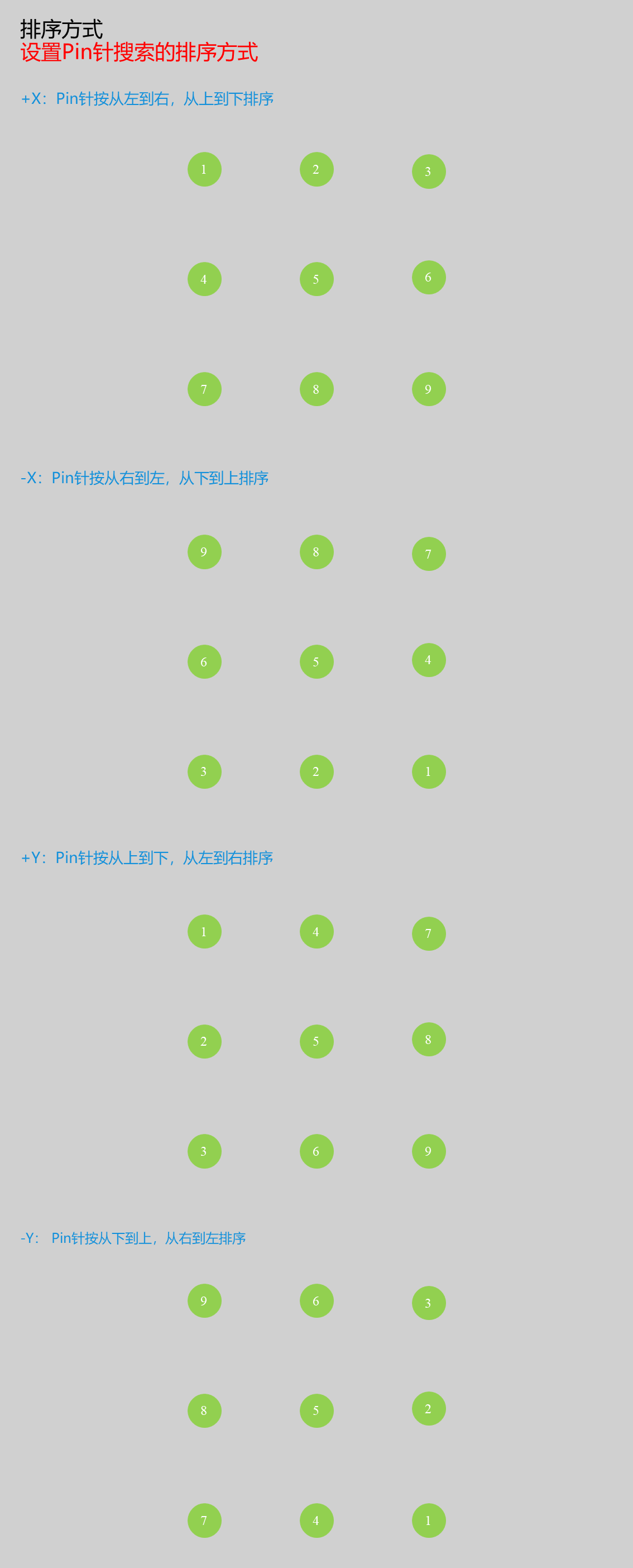 |
Result Display
| Parameter | Range | Default Value | Description | Illustration |
|---|---|---|---|---|
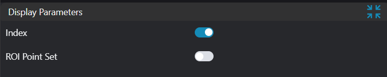
| Index | true/false | false | Blob index. If enabled, display in the image | |
| ROI Point Set | true/false | false | Region point set selected by ROI box. If enabled, display in the image |
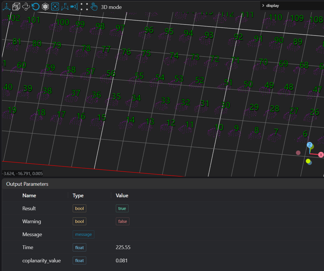
Output Parameters
| Name | Type | Range | Description |
|---|---|---|---|
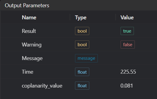
| Result | bool | true/false | true for success false for failure |
| Warning | bool | true/false | true indicates a warning false indicates no warning |
| Message | string | Output success, error, or warning messages. Empty if no error or warning. | |
| Time | float | Operator execution time, unit: ms | |
| coplanarity_value | float | Coplanarity value |
Exception Troubleshooting
| No. | Exception Information | Corresponding Parameter | Solution |
|---|---|---|---|
| 1 | Input value is {0}, invalid region type | Region Type | Only window2d, box, pointset supported |
| 2 | Region is empty | 1. Check if input points are empty 2. Check if ROI region selects point cloud 3. Check if bound pointset is empty | |
| 3 | Input value is {0}, invalid sorting method | Sorting Method | Only +X, -X, +Y, -Y supported |
| 4 | Blob search failed | Check if distance threshold in blob parameters is set too small |
Example Introduction
Engineering Design
Select the
Load 3D Point Cloudtool to load the required 3D point cloud image to IM0.Select the
3D Coplanaritytool.
Tool Usage
Select the input image for the operation. The image number must match the IM number where the image is located in the project.
Select the region type as Box, move the box to the position to be measured, enclosing the point cloud to be tested.
Usage Tips
- Use the ROI controller on the image window to drag or scale the box;
- Directly modify the box's start or end point coordinates in the calculation parameters to adjust the box position and size;
Set the parameters.
Check the content you want to display in the result display section.
Click
Testto check if the image window and parameters meet expectations.If there are no issues, click
Save. Run the operator in the run list, and then view the running results in the corresponding IM.