3D Multi-Point Positioning
Operator Function
This is an integrated operator that manually selects regions/manually inputs points/obtains coordinates of 2~9 points from registers, calculates the average value of these coordinates, outputs the center point coordinates, and performs position adjustment for the entire point cloud centered around this point.
Parameter Introduction
Input Parameters

| Parameter | Range | Default Value | Description | Illustration |
|---|---|---|---|---|
| Input Image | 0-8 | 0 | IM number for image input | |
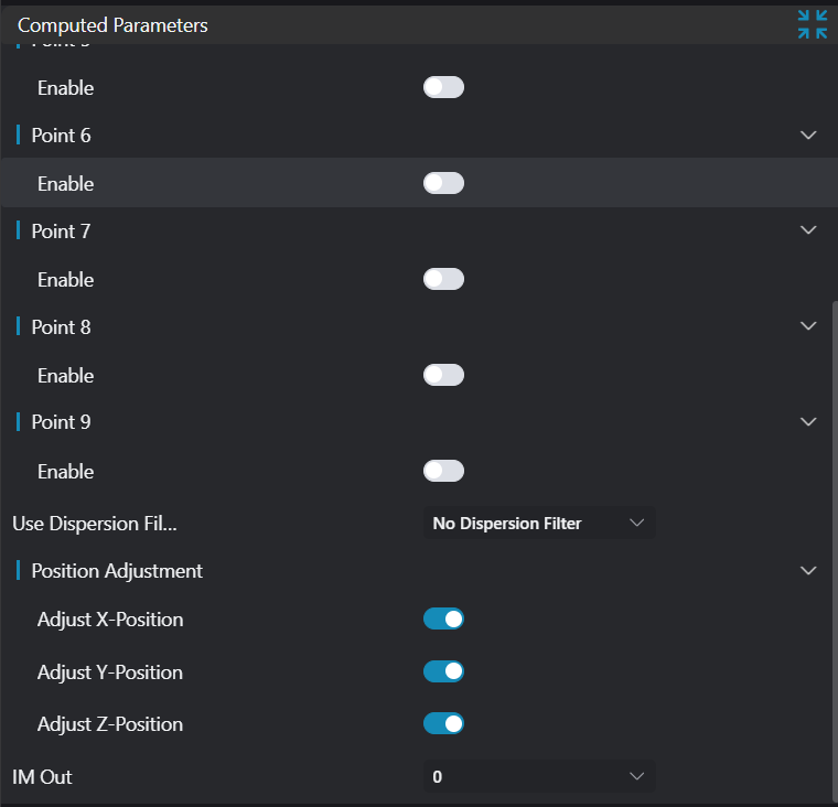
Calculation Parameters
| Parameter | Range | Default Value | Description | Illustration |
|---|---|---|---|---|
| Point n | Point/3D Square Probe | 3D Square Probe | Input point position coordinates or | |
| Filter Method | No Filter/Statistical Filter/RANSAC Filter | No Filter | No Filter: No filtering of found edge points Statistical Filter: This filtering method first performs a best fit on the found edge points, then uses the standard deviation multiplication factor to calculate the distance threshold. Calculate the distance from all edge points to the fitted model. If this distance is greater than the distance threshold, it is considered an outlier. RANSAC: This filtering method is divided into two steps: hypothesis and verification. The hypothesis process involves randomly selecting n points from the point set for geometric model fitting; the verification process uses the remaining point set to calculate the distance to this geometric model. Points with distances less than the distance threshold are called inliers. If the number of inliers meets the threshold, the geometric model obtained from this hypothesis process is the best model, and iteration stops. | |
| Standard Deviation Multiple | 2.000 | |||
| Distance Threshold | 0.100 | If the distance from a point to the output geometry is greater than this threshold, it will be filtered out. | ||
| Iteration Count | 50 | If the iteration count exceeds this number, the algorithm will stop iterating. | ||
| Position Adjustment | Adjust X Position: If enabled, adjust the X coordinate of the new origin to 0 Adjust Y Position: If enabled, adjust the Y coordinate of the new origin to 0 Adjust Z Position: If enabled, adjust the Z coordinate of the new origin to 0 | |||
| Output Image | 0-8 | 0 | IM number for image output |
Point n
| Parameter | Range | Default Value | Description | Illustration |
|---|---|---|---|---|
| Enable | true/false | false | If enabled, activate this point | |
| Point | Input point position coordinates | |||
| 3D Square Probe | 2D Window: Input point cloud within the window, extract points from this point cloud Box: Input point cloud within the box, extract points from this point cloud |
As shown in the figure below: Input four points A, B, C, D, then obtain the center point O (x, y, z)

In the initial state, the X, Y, Z coordinates will be adjusted. The figure below shows the positions of each point after adjustment.

For adjusting X, Y, Z coordinates, you can choose arbitrarily:
- Transform x:

- Transform y:

- Transform z:

- Transform xy:

- Transform xz:

- Transform yz:

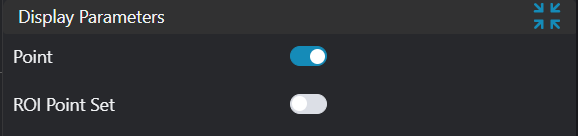
Result Display
| Parameter | Range | Default Value | Description | Illustration |
|---|---|---|---|---|
| Positioning Point | true/false | false | If enabled, display the positioning point in the image | |
| ROI Point Set | true/false | false | Region point set selected by ROI box. If enabled, display in the image |
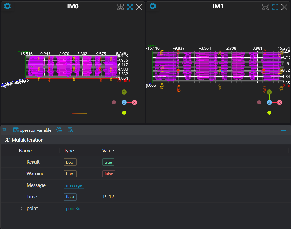
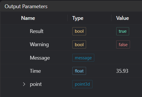
Output Parameters
| Name | Type | Range | Description |
|---|---|---|---|
| Result | bool | true/false | true for success false for failure |
| Warning | bool | true/false | true indicates a warning false indicates no warning |
| Message | string | Output success, error, or warning messages. Empty if no error or warning. | |
| Time | float | Operator execution time, unit: ms | |
| point | point3d | Output positioning point |
Tip
For more detailed explanations of parameter types, please refer to Type Definitions
Exception Troubleshooting
| No. | Exception Information | Corresponding Parameter | Solution |
|---|---|---|---|
| 1 | Input filter mode is {0}, invalid filter mode | Filter Mode | Choose filter mode as one of: No Filter/RANSAC/Statistical Filter |
| 2 | Input point cloud is empty | Confirm if IM contains valid points. If no valid points, load point cloud or switch to IM with valid points | |
| 3 | Input region {0} type is {1}, invalid region type | Index, Region Type | Region input type must be one of: 2D Window/2D Circular Window/Box/Cylindrical Box/Point Set |
| 4 | Input region number {0} is empty | Index | Check if this region number selects point cloud |
| 5 | Point {0} input mode is {1}, invalid mode input | Index, Mode | Mode must be Point/3D Square Probe |
| 6 | Number of selected points is less than 2 | Enable at least 2 points | |
| 7 | Polygon window vertex count for point {0} is less than 3, cannot form polygon | Index | Check the polygon window, increase its vertex count to 3 or more |
Example Introduction
Engineering Design
Select the
Load Point Cloudtool to load the required 3D point cloud image to IM0.Select the
3D Multi-Point Positioningtool.
Tool Usage
Select the input image for the operation. The image number must match the IM number where the image is located in the project.
Enable multiple points, select 3D Square Probe type as Box, move the box to the position of the positioning point, enclosing the positioning point area.
Usage Tips
- Use the ROI controller on the image window to drag or scale the box;
- Directly modify the box's start or end point coordinates in the calculation parameters to adjust the box position and size;
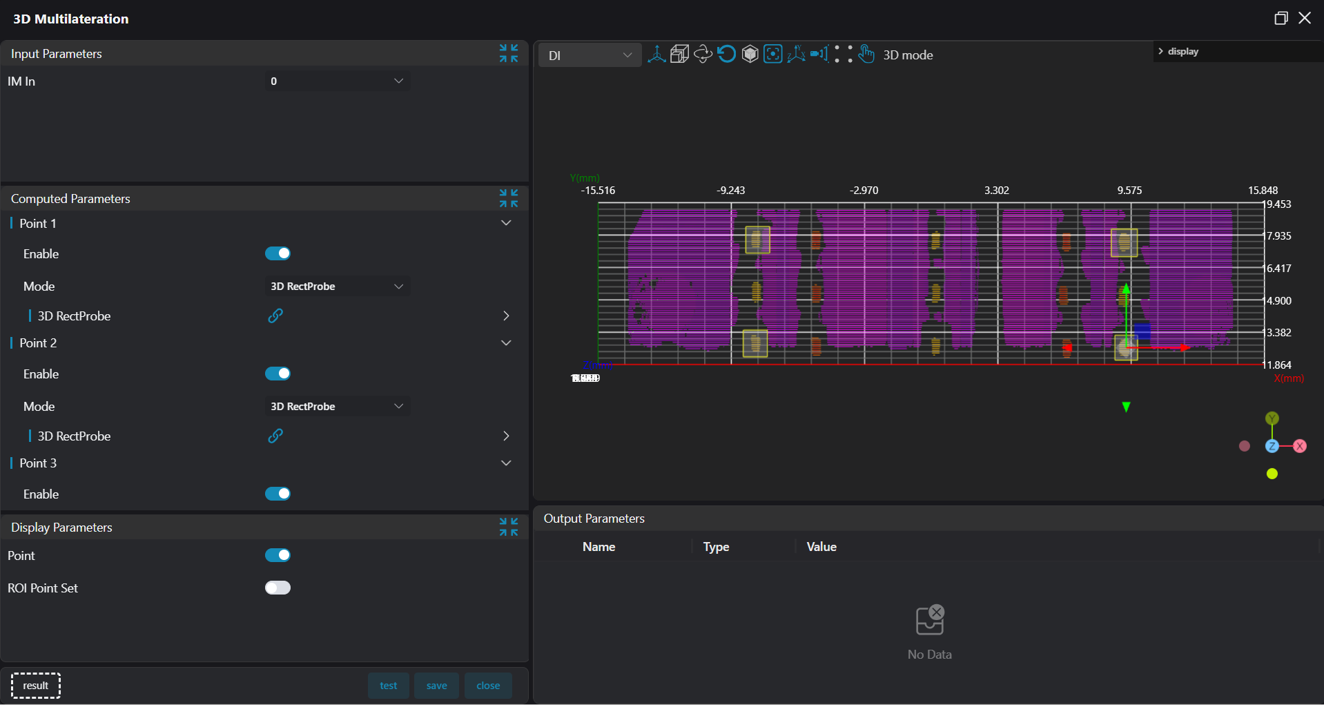
Set the parameters.
Check the content you want to display in the result display section.
Click
Testto check if the image window and parameters meet expectations.If there are no issues, click
Save. Run the operator in the run list, and then view the running results in the corresponding IM.