Solder Joint Inspection
Operator Function
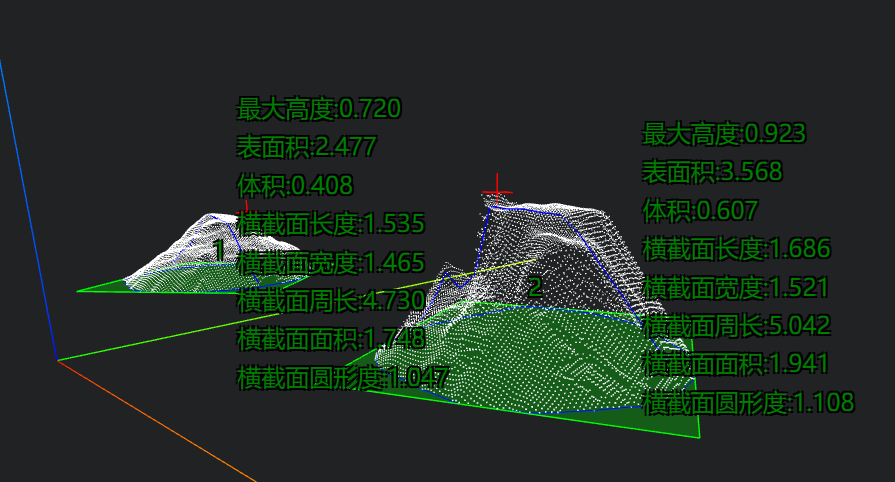
Input solder joint point cloud, output various parameters of the solder joint based on set parameters, draw cross-sections, obtain cross-section length, width, circularity, highest point of solder joint, volume, and surface area. 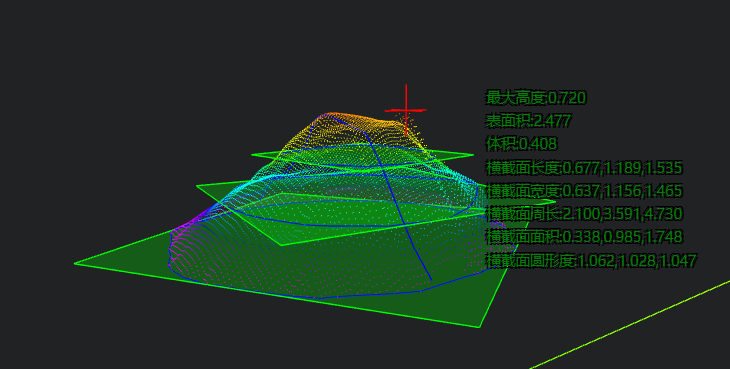
Parameter Introduction
Input Parameters

| Parameter | Range | Default Value | Description | Illustration |
|---|---|---|---|---|
| Input Image | 0-8 | 0 | The IM number for image input | |
Calculation Parameters
| Parameter | Range | Default Value | Description | Illustration |
|---|---|---|---|---|
| Use Region Parameter | true/false | false | If enabled, use Region as input; if disabled, use Input Image as input | |
| Region | 2D Window/2D Circular Window/2D Polygon Window/Box/Cylinder Box/Rotated Box/Point Set | Box | Manually select appropriate ROI regionCan bind to select existing ROI regions | |
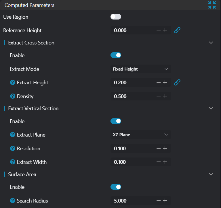
| Reference Height | 0.000 | Set the reference height of the image (affects height measurement and judgment) | ||
| Cross-section Extraction | See Cross-section Extraction | |||
| Longitudinal Section Extraction | See Longitudinal Section Extraction | |||
| Surface Area | Calculate solder joint surface area: See Surface Area | |||
| Volume | Calculate solder joint volume: See Volume |
Cross-section Extraction
| Parameter | Range | Default Value | Description | Illustration |
|---|---|---|---|---|
| Enable | true/false | false | Enable cross-section extraction | |
| Extraction Mode | Fixed Height/Multiple Cross-sections | Fixed Height | Set cross-section extraction height | |
| Number of Cross-sections | 2/3/4/5 | 3 | Enabled when Extraction Mode is Multiple Cross-sections, set number of cross-sections to extract | |
| Extraction Mode | Manual/Automatic | Automatic | Enabled when Extraction Mode is Multiple Cross-sections, set input mode for multiple cross-section heights. When automatic, solder joint will be automatically divided equally by height to extract cross-sections | |
| Extraction Position | 0.000 | Enabled when Extraction Mode is Fixed Height, set cross-section extraction height | ||
| Extraction Position 1-5 | 0.000 | Enabled when Extraction Mode is Multiple Cross-sections and Extraction Mode is Manual, manually input heights for multiple cross-section extraction | ||
| Density | 0.1-1 | 0.500 | Set cross-section extraction density. Higher values result in denser point cloud for each cross-section contour | 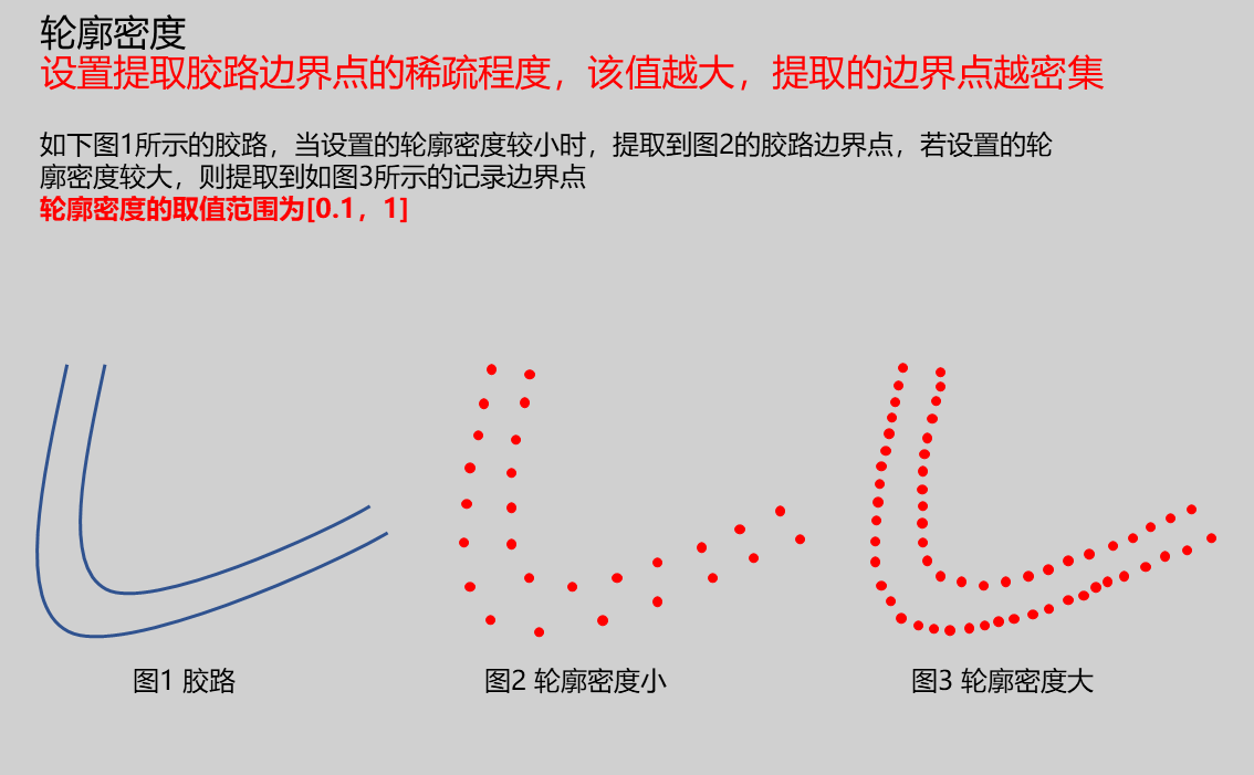 |
Longitudinal Section Extraction
| Parameter | Range | Default Value | Description | Illustration |
|---|---|---|---|---|
| Enable | true/false | false | Enable longitudinal section extraction | |
| Extraction Plane | XZ Plane/YZ Plane | XZ Plane | Select cutting plane, will cut along this direction XZ Plane: Set cutting plane as XZ plane YZ Plane: Set cutting plane as YZ plane | 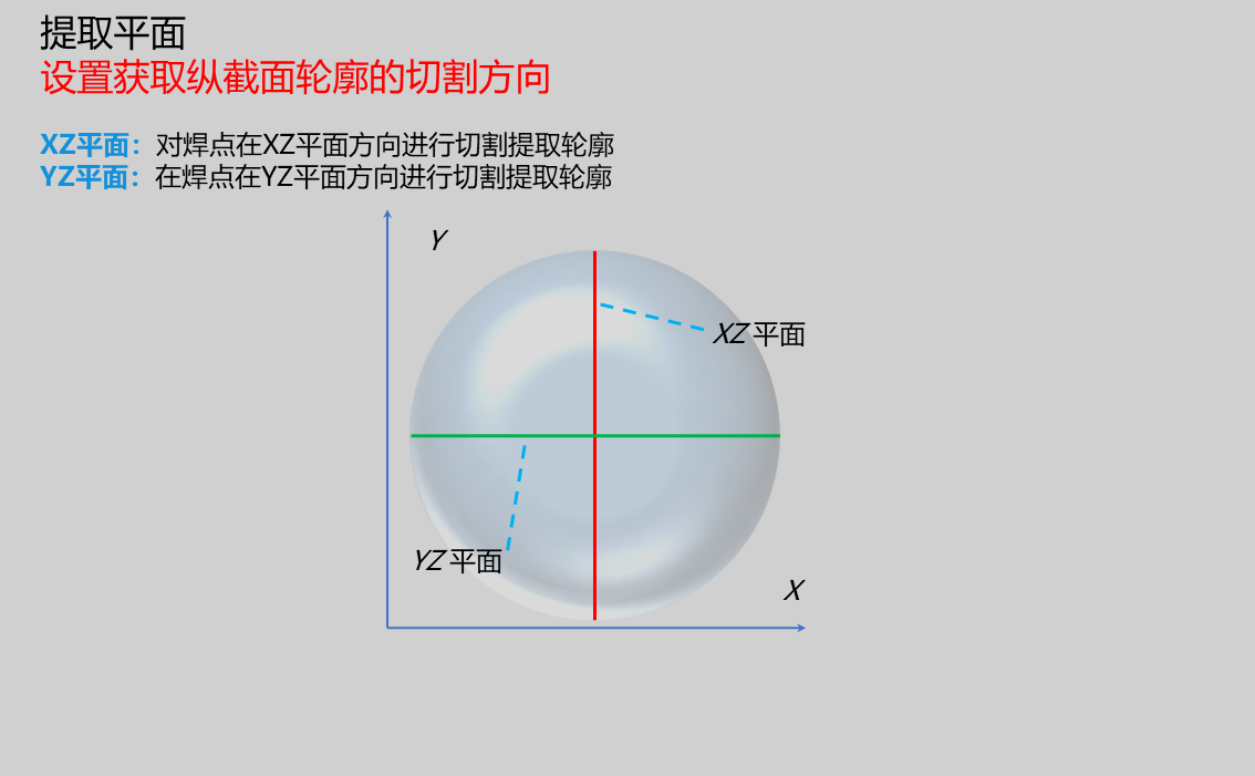 |
| Resolution | 0.100 | When extraction plane is XZ plane, this resolution is the x-direction resolution of fitted contour; when extraction plane is YZ plane, this resolution is the y-direction resolution of fitted contour |  | |
| Extraction Width | 0.100 | Set cutting width value. Points within the positive and negative range of this value at the cutting position will be used as extracted contour points | 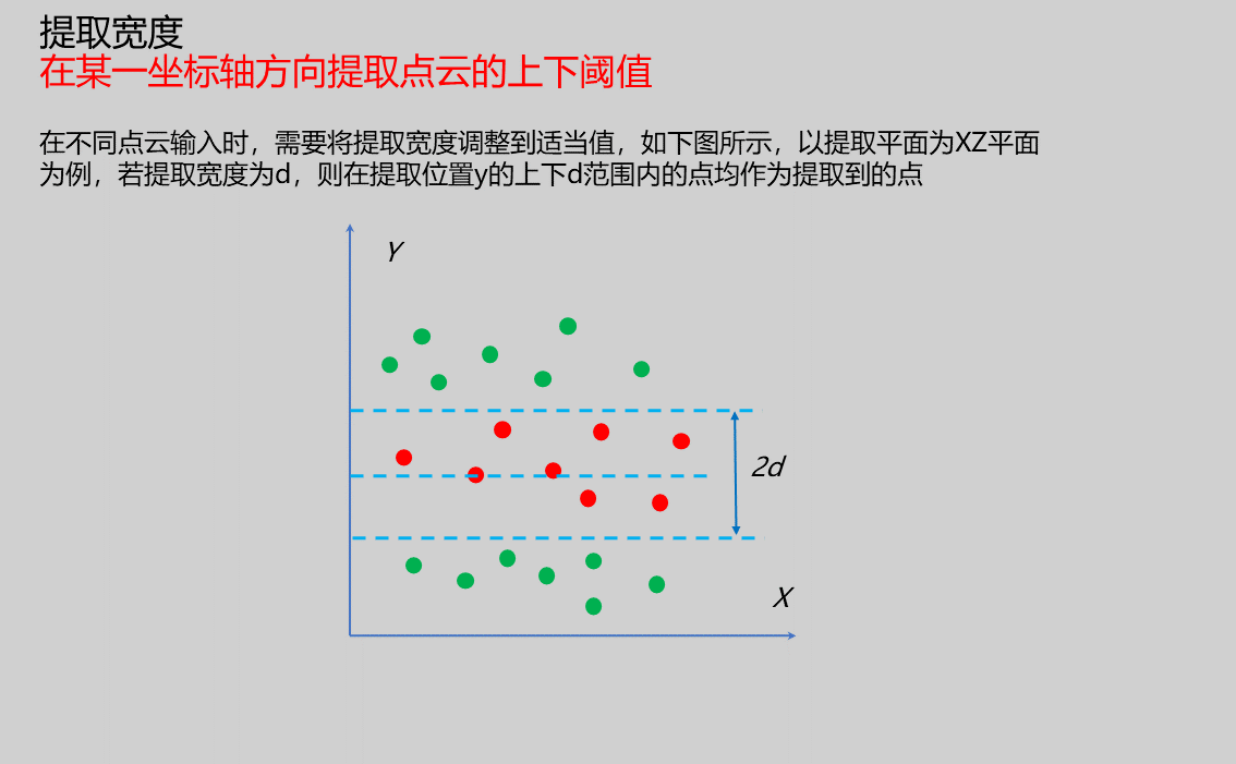 |
Surface Area
| Parameter | Range | Default Value | Description | Illustration |
|---|---|---|---|---|
| Enable | true/false | false | Enable surface area calculation | |
| Search Radius | 0-100 | 5.000 | Set sphere radius for determining k-nearest neighbors. Depending on point cloud density and distribution, this value may need adjustment. For example, sparser point clouds may require larger search radius. As shown below, blue circle is centered with search radius as radius, red points are within search radius, green points are outside. Larger search radius considers more points for triangulation. | 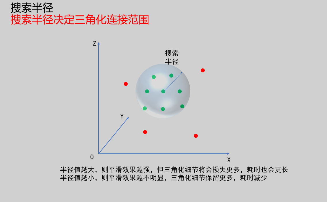 |
| Maximum Neighbors | 1-100 | 30 | Set maximum number of neighbors for solder joint point cloud normal vector estimation. Larger values may improve robustness of normal estimation, especially for sparse or irregular point clouds. However, excessively large values may increase computational load and introduce unnecessary noise. Smaller values may improve computational efficiency but may lead to less accurate normal estimation in some cases. | 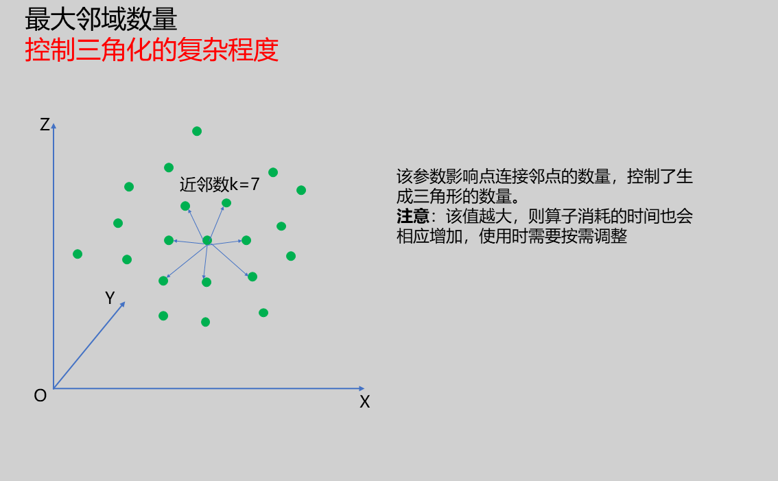 |
| Nearest Neighbor Distance Product Coefficient | 0-100 | 3.500 | Dynamically adjust maximum search distance for each sample point. Larger values result in larger maximum search distances. When set to larger value: Search radius increases, meaning algorithm considers more neighboring points to construct point cloud surface, which may be beneficial in sparser regions. However, if set too large, may cause over-connection and inaccurate surface. When set to smaller value: Search radius decreases, algorithm considers fewer neighboring points. This may be beneficial in denser regions or when finer reconstruction is needed. But if set too small, may miss some points that should be connected, resulting in incomplete surface. | 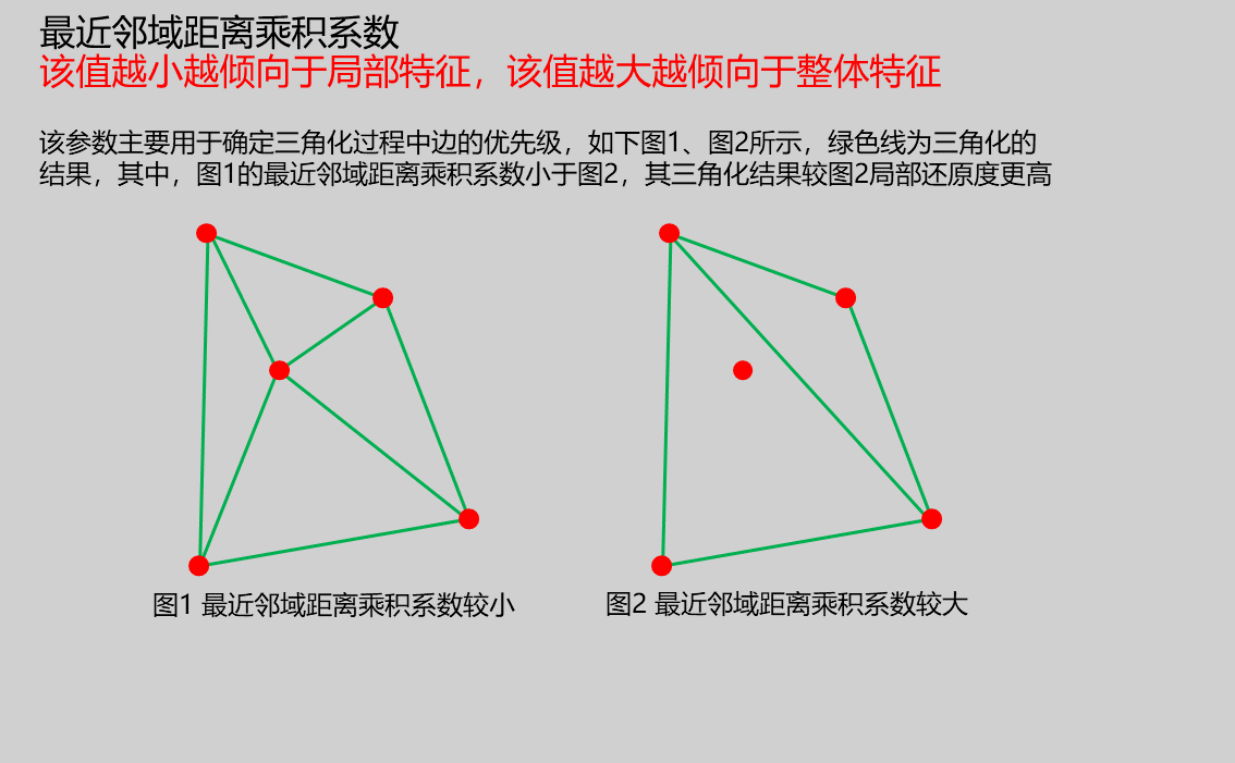 |
Volume
| Parameter | Range | Default Value | Description | Illustration |
|---|---|---|---|---|
| Enable | true/false | false | Enable volume calculation | |
| X Resolution | 0.100 | Set X-direction resolution for volume measurement | 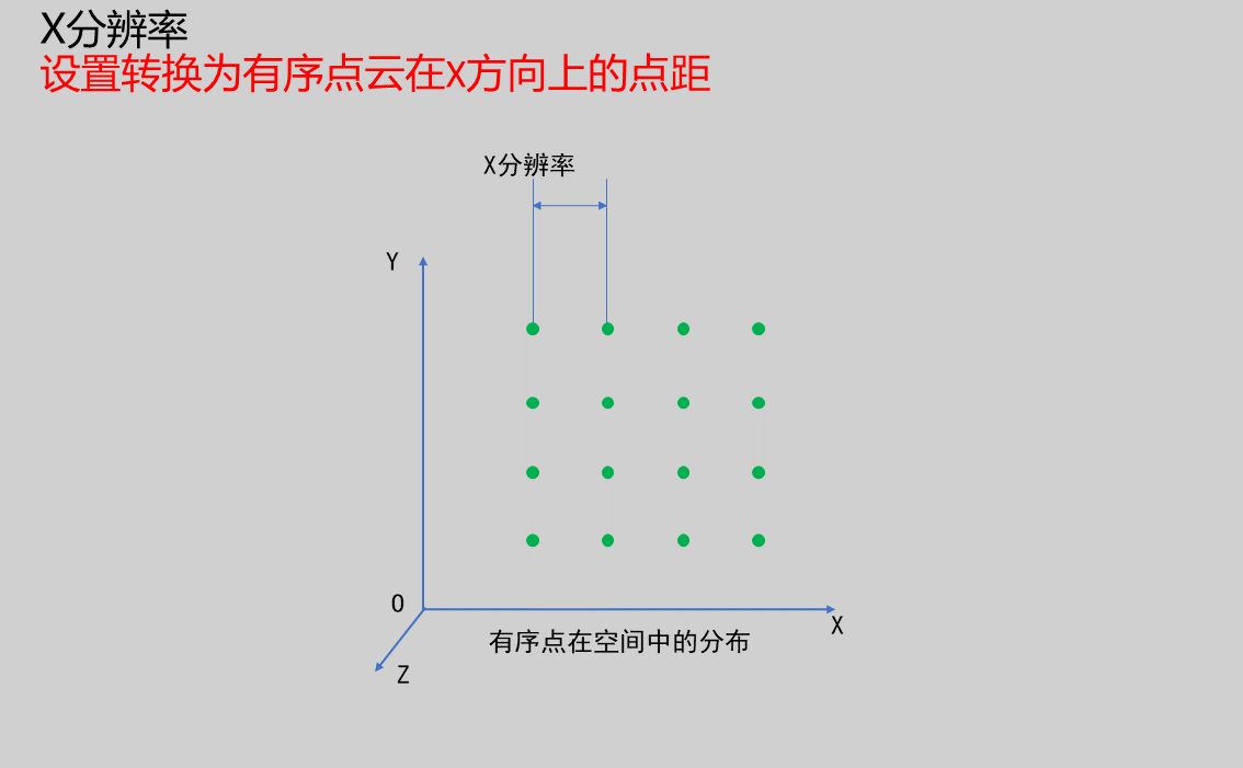 | |
| Y Resolution | 0.100 | Set Y-direction resolution for volume measurement | 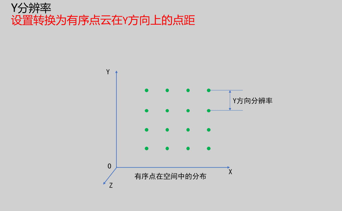 | |
| Number of Slice Contours | 2-100000 | 1000 | Number of contours to be cut. More contours result in more precise volume calculation. But increasing number increases computational load, adjust according to actual situation. | 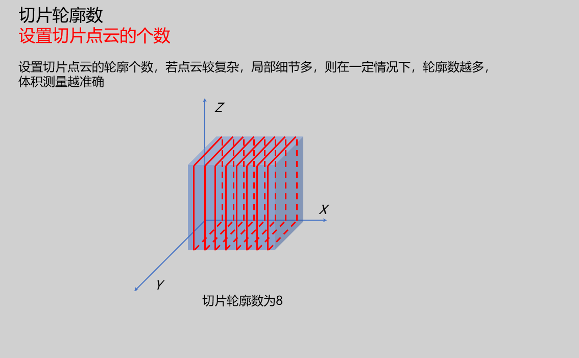 |
| Slice Direction | X/Y/Z | X | Normal direction of cutting plane. Currently can be set to X, Y, and Z. As shown below, slice direction is X direction. | 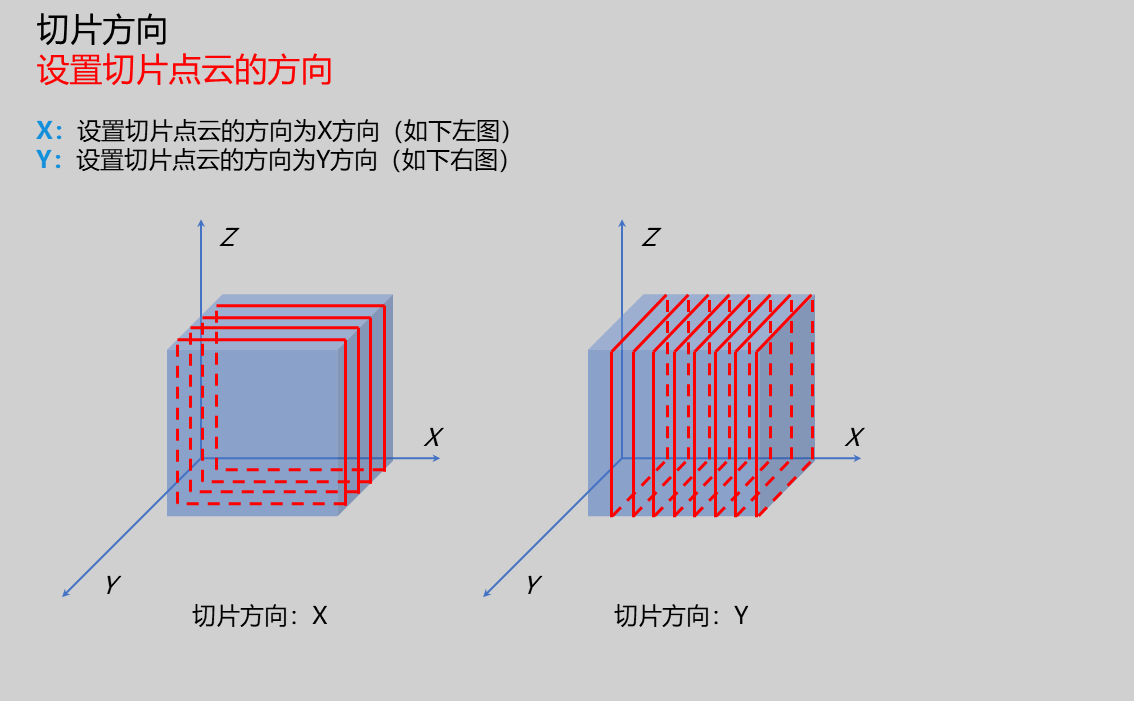 |
Result Display
| Parameter | Range | Default Value | Description | Illustration |
|---|---|---|---|---|
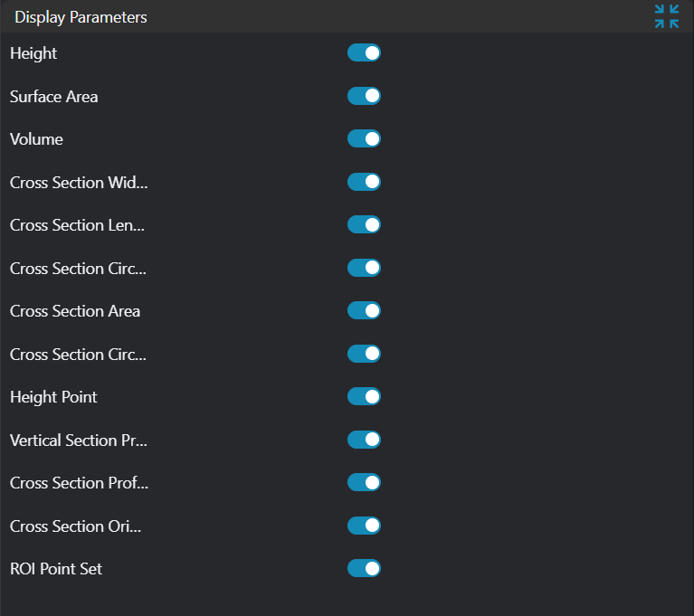
| Height | true/false | false | Solder joint height value, display in image if enabled | |
| Surface Area | true/false | false | Solder joint surface area value, display in image if enabled | |
| Volume | true/false | false | Solder joint volume value, display in image if enabled | |
| Cross-section Width | true/false | false | Solder joint cross-section width value, display in image if enabled | |
| Cross-section Length | true/false | false | Solder joint cross-section length value, display in image if enabled | |
| Cross-section Perimeter | true/false | false | Solder joint cross-section perimeter value, display in image if enabled | |
| Cross-section Area | true/false | false | Solder joint cross-section area value, display in image if enabled | |
| Cross-section Circularity | true/false | false | Solder joint cross-section circularity value, display in image if enabled | |
| Height Measurement Point | true/false | false | Height point, display in image if enabled | |
| Cross-section Contour | true/false | false | Cross-section contour, display in image if enabled | |
| Longitudinal Section Contour | true/false | false | Longitudinal section contour, display in image if enabled | |
| Cross-section Minimum Bounding Rectangle | true/false | false | Cross-section minimum bounding rectangle, display in image if enabled | |
| ROI Point Set | true/false | false | Only effective when Use Region Parameter is enabled. ROI selected region point set, display in image if enabled |
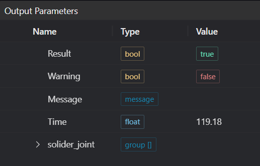
Output Parameters
| Name | Type | Range | Description |
|---|---|---|---|
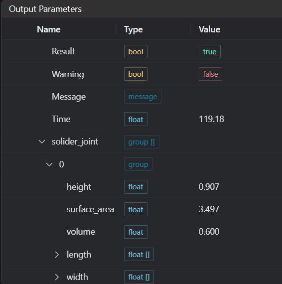
| Result | bool | true/false | true for success false for failure |
| Warning | bool | true/false | true indicates a warning false indicates none |
| Message | string | Output success, error, or warning messages. Empty if no error or warning | |
| Time | float | Operator execution time, unit: ms | |
| solider_joint | group | Output solder joint information | |
| surface_area | float | Output solder joint surface area | |
| height | float | Output solder joint height | |
| volume | float | Output solder joint volume | |
| cross_section_length | float[] | Output solder joint cross-section length | |
| cross_section_width | float[] | Output solder joint cross-section width | |
| cross_section_area | float[] | Output solder joint cross-section area | |
| cross_section_circumference | float[] | Output solder joint cross-section perimeter | |
| cross_section_circularity | float[] | Output solder joint cross-section circularity | |
Note: When input is an array, parameters for each solder joint will form an array, with each array being a set of measurement data for a group of solder joints |
Tip
For more detailed explanations of parameter types, please refer to Type Definitions
Exception Troubleshooting
| No. | Exception Information | Corresponding Parameter | Solution |
|---|---|---|---|
| 1 | Input region type is {0}, invalid region type | Region Type | Region input type must be one of: 2D Window/2D Circular Window/2D Polygon Window/Box/Cylinder Box/Rotated Box/Point Set |
| 2 | Region {0} is empty | Region Number | 1. Check if selection is empty 2. Check if point set is empty |
| 3 | Input point cloud is empty | Confirm if IM contains valid points. If no valid points, load point cloud or switch to IM with valid points | |
| 4 | Input cross-section height is invalid | Adjust cross-section height | |
| 5 | Current surface area parameters failed to calculate surface area | Adjust surface reconstruction parameters: 1. Search Radius 2. Maximum Neighbors 3. Nearest Neighbor Distance Product Coefficient | |
| 6 | Output area value is too large | Recommend calculating surface area in segments | |
| 7 | Set X or Y resolution is invalid | Select appropriate X or Y resolution | |
| 8 | Input slice direction is {0}, invalid slice direction | Slice Direction | Select slice direction as XY |
| 9 | Extracted contour is empty | Adjust cutting width | |
| 10 | Ordered point cloud input required | Input using ordered point cloud image | |
| 11 | Input extraction mode is {0}, invalid extraction mode | Extraction Mode | Select extraction mode as Fusion-Average/Nearest |
| 12 | Input extraction position has no contour or resolution is much smaller than point spacing | Adjust extraction position or resolution | |
| 13 | Input extraction plane is {0}, invalid extraction plane | Extraction Plane | Select extraction plane as XZ/YZ plane |
| 14 | Input cross-section extraction mode is {0}, invalid extraction mode | Extraction Mode | Select cross-section extraction mode as Fixed Height/Multiple Cross-sections |
| 15 | Solder joint point count is too low | Select point cloud with more points as input | |
| 16 | Input polygon vertex count is less than 3, cannot form polygon | Add 2D polygon window vertices so vertex count is at least three | |
| 17 | Input extraction position mode is {0}, invalid input mode | Select extraction position mode as Automatic/Manual |
Example Introduction
Engineering Design
Select
Load Point Cloudtool to load required 3D point cloud image into IM0;Select
3D Regiontool to select region requiring plane fitting;Select
3D Planetool, using output of3D Regiontool as input, fit plane and transform point cloud;Select
3D Cuttool to cut out solder joint point cloud;Select
3D Blobtool to obtain target solder joint 1 and target solder joint 2 point clouds;Select
Solder Joint Inspectiontool.
Tool Usage
Select input image for operation. Image number must match IM number where image is located in project.
Either disable Use Region Parameter or enable Region and select region type as Box, then move box to target position to surround point cloud to be measured.
Usage Tips
- Use ROI controller on image window to drag or scale box;
- Directly modify box start or end coordinates in calculation parameters to adjust box position and size.
Set parameters.
Check desired display content in Result Display section.
Click
Testto check if image window and parameters meet expectations.If everything is correct, click
Save, then run operator in run list. View results in corresponding IM.