3D Surface Defect
Operator Function
Detect convex and concave defects in the input point cloud image, and output specified type defect information to global variables.
Parameter Introduction
Input Parameters

| Parameter | Range | Default Value | Description | Illustration |
|---|---|---|---|---|
| Input Image | 0-8 | 0 | The IM number for image input | |
Calculation Parameters
| Parameter | Range | Default Value | Description | Illustration |
|---|---|---|---|---|
| Use Region Parameters | true/false | false | If enabled, use Region as input; if not enabled, use Input Image as input | |
| Region | 2D Window/Box | Box | Manually select an appropriate ROI regionCan bind to select existing ROI regions | |
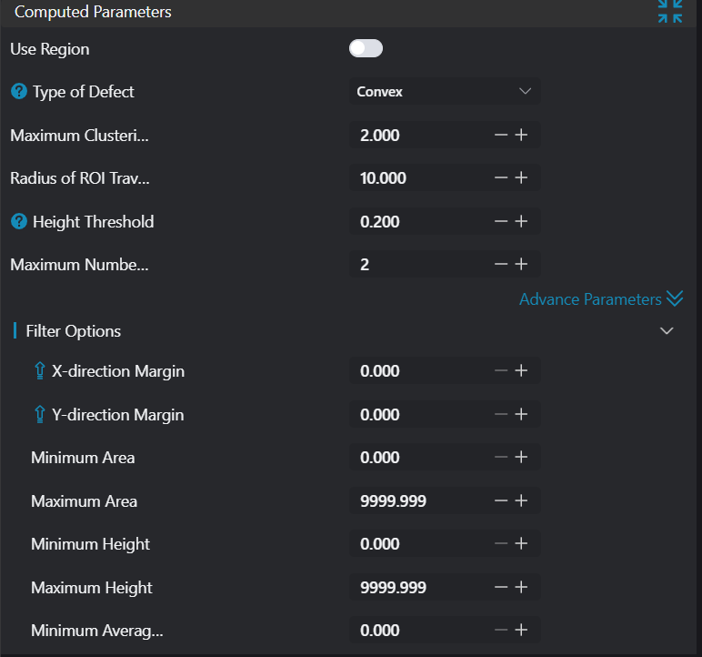
| Defect Type | Concave/Convex/Concave+Convex | Concave+Convex | Concave: Point cloud regions below the reference plane Convex: Point cloud regions above the reference plane Concave+Convex: Point cloud regions both above and below the reference plane |  |
| Defect Length | 0.500 | Long side size of the largest defect in the current detection area. Unit: mm. | ||
| ROI Traversal Radius | 0.500 | ROI traversal radius during point cloud preprocessing in the current detection area. Unit: mm. | ||
| Height Detection Threshold | 0.500 | Defect point cloud regions greater than this threshold will be preserved; those less than this threshold will be discarded. | 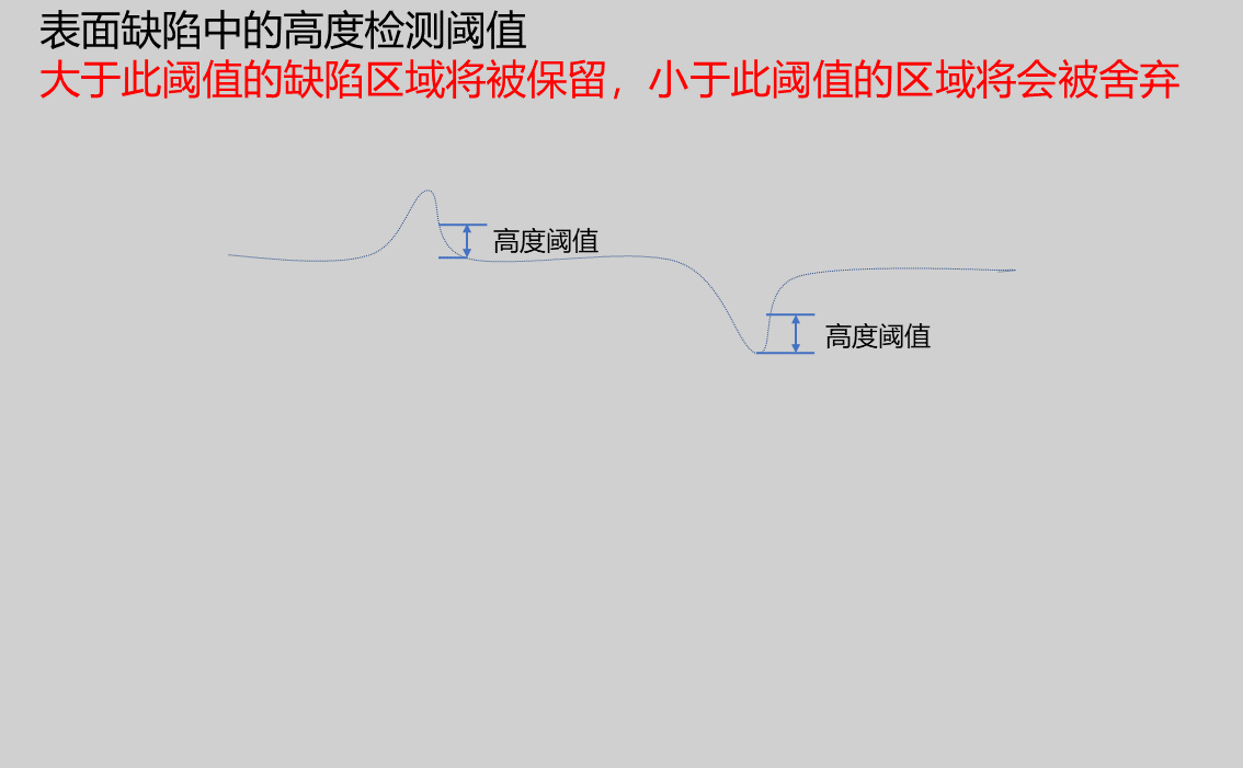 | |
| Maximum Detection Count | 10 | Set the maximum number of defects that can be output | ||
| Minimum Area | 0.000 | Lower limit of rectangular area formed by defect point cloud bounding box | 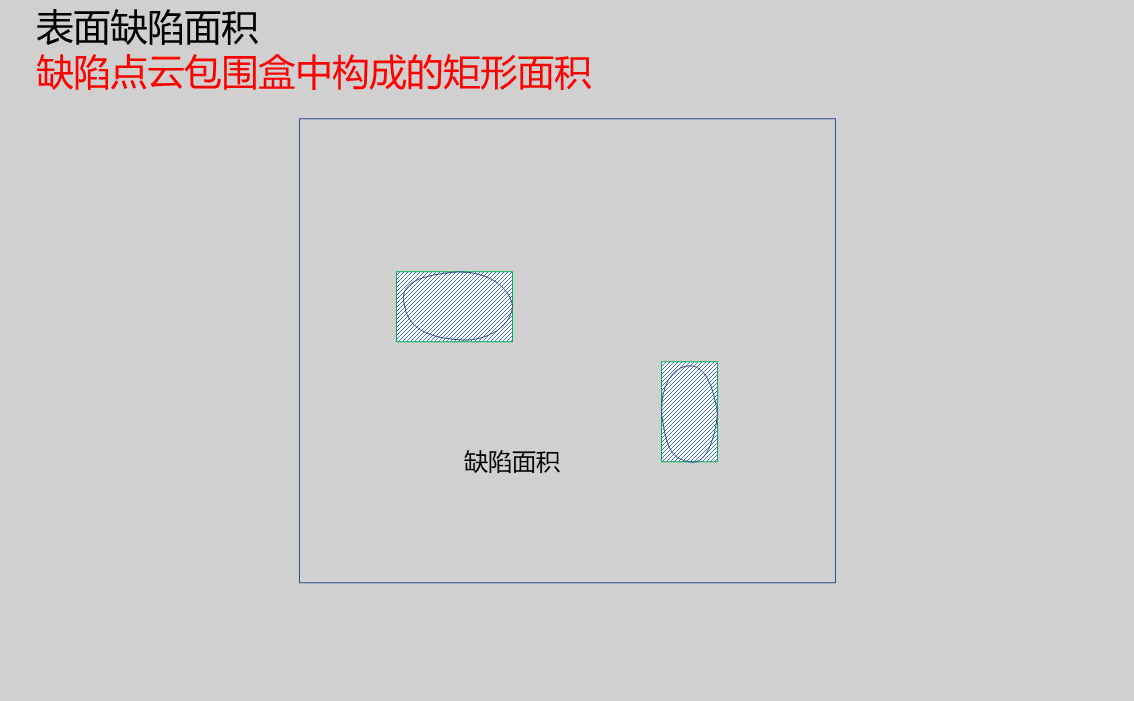 | |
| Maximum Area | 9999.999 | Upper limit of rectangular area formed by defect point cloud bounding box | | |
| Minimum Height | 0.000 | Lower limit of minimum height in defect point cloud | ||
| Maximum Height | 9999.999 | Upper limit of maximum height in defect point cloud | ||
| Minimum Average Height | 0.000 | Lower limit of average height in defect point cloud | ||
| Maximum Average Height | 9999.999 | Upper limit of average height in defect point cloud | ||
| Minimum Bounding Box Long Side | 0.000 | Lower limit of the longest side of the rectangle formed by defect point cloud bounding box | 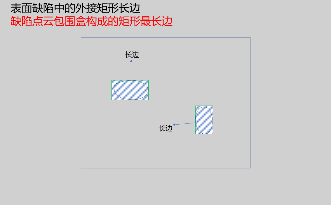 | |
| Maximum Bounding Box Long Side | 9999.999 | Upper limit of the longest side of the rectangle formed by defect point cloud bounding box | |
Result Display
| Parameter | Range | Default Value | Description | Illustration |
|---|---|---|---|---|
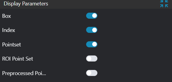
| Box | true/false | false | Target defect bounding rectangle; if enabled, displayed in the image | |
| Sequence Number | true/false | false | Defect sequence number; if enabled, displayed in the image | |
| Point Set | true/false | false | Target point set; if enabled, displayed in the image | |
| ROI Point Set | true/false | false | Only effective when Use Region Parameters is selected; the point set of the ROI selected region; if enabled, displayed in the image | |
| Preprocessed Point Cloud | true/false | false | Height difference point cloud after preprocessing; if enabled, displayed in the image |
Output Parameters
| Name | Type | Range | Description |
|---|---|---|---|
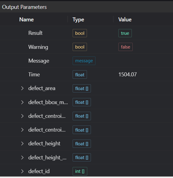
| Result | bool | true/false | true for success false for failure |
| Warning | bool | true/false | true indicates there is a warning false indicates there is none |
| Message | string | Outputs success, error, or warning information; if there is no error or warning, it is empty | |
| Time | float | Operator execution time, unit: ms | |
| defect_area | float[] | Defect area | |
| defect_bbox_max_width | float[] | Defect long side | |
| defect_centroid_x | float[] | Defect centroid x coordinate | |
| defect_centroid_y | float[] | Defect centroid y coordinate | |
| defect_height | float[] | Defect height | |
| defect_height_avg | float[] | Defect average height | |
| defect_id | float[] | Defect ID | |
| defect_num | int | Defect count |
Exception Troubleshooting
| No. | Exception Information | Corresponding Parameter | Solution |
|---|---|---|---|
| 1 | The input value is {0}, invalid region type | Region Type | Only supports window2d, box, pointset |
| 2 | Region crop failed | 1. Check if input point cloud is empty 2. Check if ROI region encloses any point cloud 3. Check if bound pointset is empty | |
| 3 | The input value is {0}, invalid defect area threshold | Minimum Area | Only supports minimum defect area < maximum defect area |
| 4 | The input value is {0}, invalid defect height threshold | Minimum Height | Only supports minimum height < maximum height |
| 5 | The input value is {0}, invalid defect average height threshold | Minimum Average Height | Only supports minimum average height < maximum average height |
| 6 | The input value is {0}, invalid minimum bounding box long side threshold | Minimum Bounding Box Long Side | Only supports minimum bounding box long side < maximum bounding box long side |
| 7 | Failed to find {1} defects with width greater than {0}. | Height Detection Threshold, Defect Type | 1. Check if height detection threshold is too large 2. Check if defect type is selected correctly |
| 8 | Failed to find {0} defects | Defect Type | Check if distance threshold in defect parameters is set too small |
| 9 | Failed to find {0} defects | Defect Type | Check if other constraints are set in advanced parameters |
Example Introduction
Engineering Design
Select the
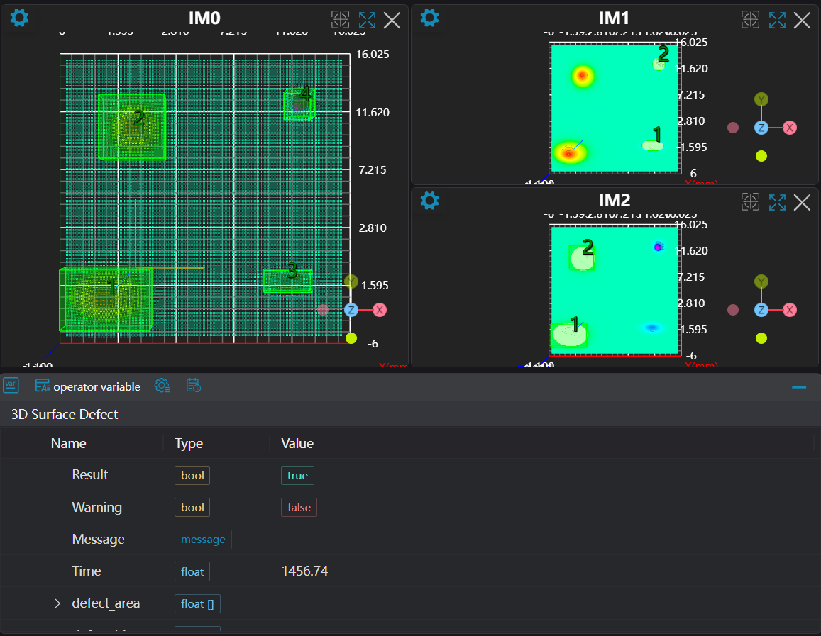
Load 3D Point Cloudtool to load the 3D point cloud image to be processed into IM0.Select the
3D Point Cloud Croptool to copy IM0 to IM1 and IM2.Select the
3D Surface Defecttool, set different defect types.
Tool Usage
Select the input image for operation; the image number must match the IM number where the image is located in the project.
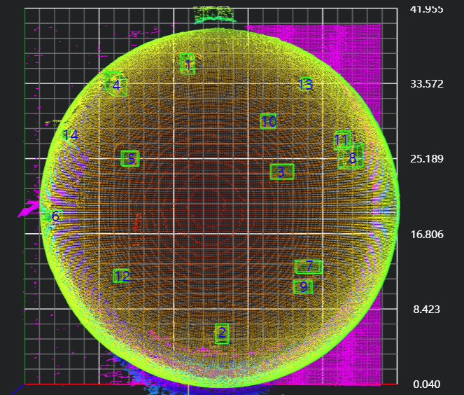
Select the region type as Box, move the box to the position to be measured, enclosing the point cloud to be measured.
Usage Tips
- Use the ROI controller on the image window to drag or scale the box;
- Directly modify the start or end coordinates of the box in the calculation parameters to adjust the box position and size;
Set parameters
Check the content you want to display in the result display section
Click
Testto check if the image window and parameters meet expectationsIf there are no issues, click
Save, then run the operator in the run list to view the results in the corresponding IM