BGA Solder Ball Coplanarity Detection
Project Introduction
Project Background
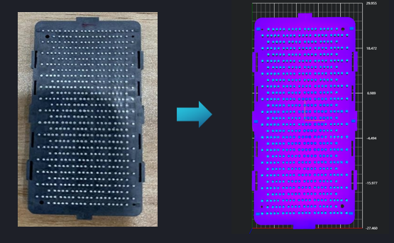
Poor coplanarity of solder balls may lead to soldering defects, short circuits, and other issues, seriously affecting the performance and lifespan of products. The measured data will be statistically analyzed, including maximum, minimum, and average values, to evaluate whether the coplanarity of solder balls meets product requirements.
Camera Selection
LMI Laser Line Scan Camera Gocator2520
Detection Requirements
Measurement Accuracy ≤ 0.03mm
Measurement Repeatability ≤ 0.02mm
Measurement Cycle ≤ 2s
Solution
AI-Vision adopts an integrated tool approach, where one tool directly calculates the coplanarity of the entire balls, greatly improving speed while simplifying engineering logic.
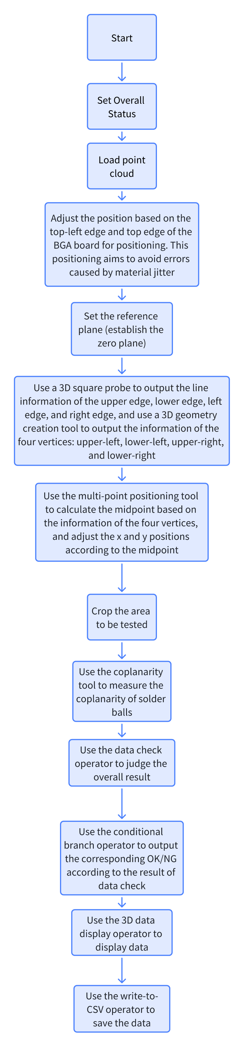
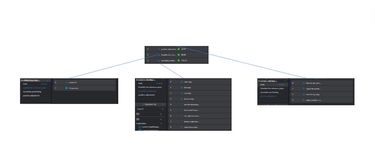
Design Idea
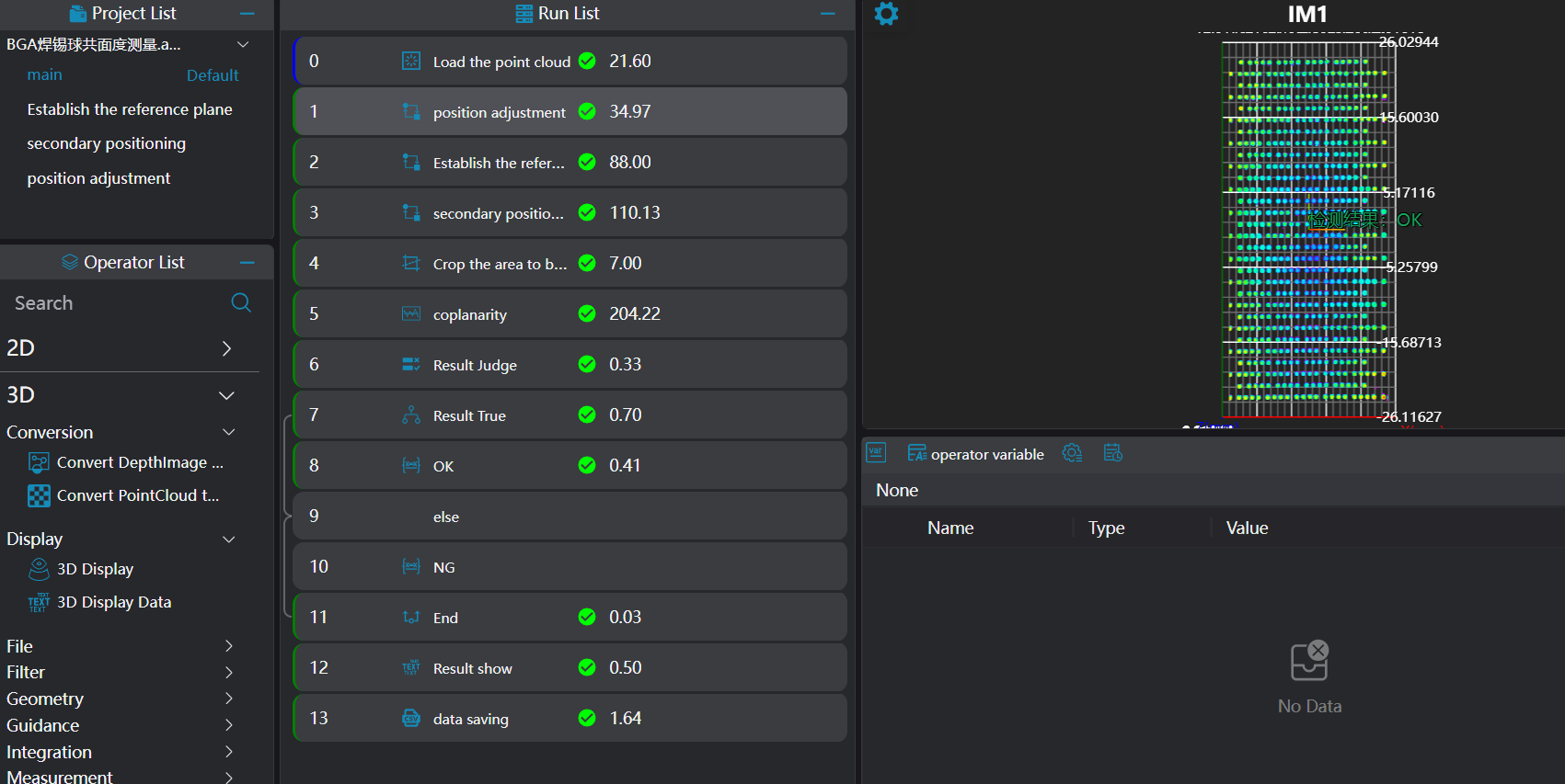
Execution Effect Display
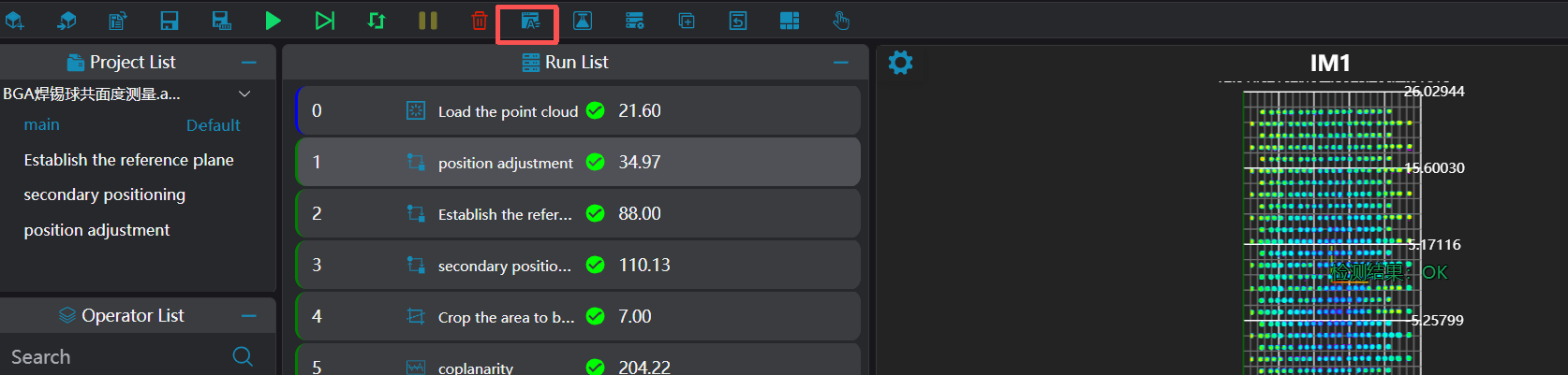
Project Result Display:
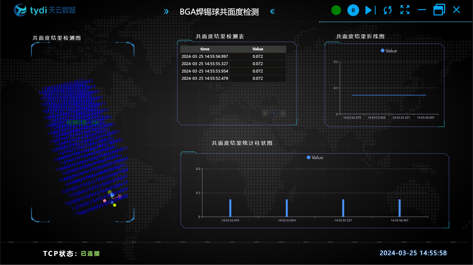
HMI Result Display:
Operation Process
1. Initialization
- Set the status variable Result in
Global Variables
- Select the
Load Point Cloudtool to obtain the point cloud.
2. Preprocessing
Position Adjustment
During actual project operation, the workpiece placement position may deviate. Therefore, the 3D position of the point cloud can be adjusted by finding a single point or line to ensure that the origins of different images are at the same position.
Use the
3D Square Probe Toolto obtain the left and upper edges of the workpiece.Use the
3D Geometric Intersection Tool, bind the two edges output by the operator variable in the previous step as input geometries, and output the intersection point of the two lines.Use the
3D Position Adjustment Tool, bind the line intersection point output by the operator in the previous step as the new origin to adjust the XY direction position of the point cloud.
Plane Fitting
During actual project operation, the workpiece placement may deviate in the z-axis direction, i.e., the up and down position. It is necessary to establish the z-axis zero plane as the datum plane to ensure that the heights (z-values) of the point cloud on the same plane are the same.
Select the
3D Regiontool and select 6 protruding columns on the PCB as the region for plane fitting.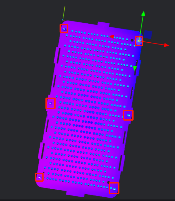
Select the
3D Planetool, bind the region obtained in the previous step as the input region to fit the plane, and use the fitted plane as the zero plane.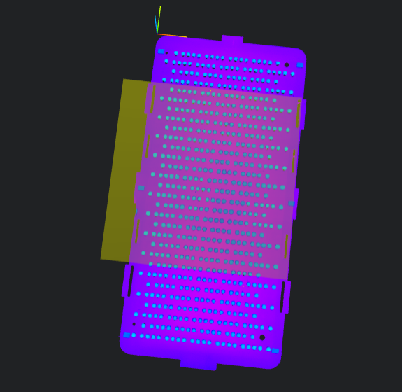
Secondary Positioning
For this case, the XY origin required by the customer is at the center of the point cloud. Therefore, secondary positioning is required to adjust the datum position.
- Select the
3D Square Probetool, select the region box on the four edges, and execute the tool to find the four edges: top, bottom, left, and right.
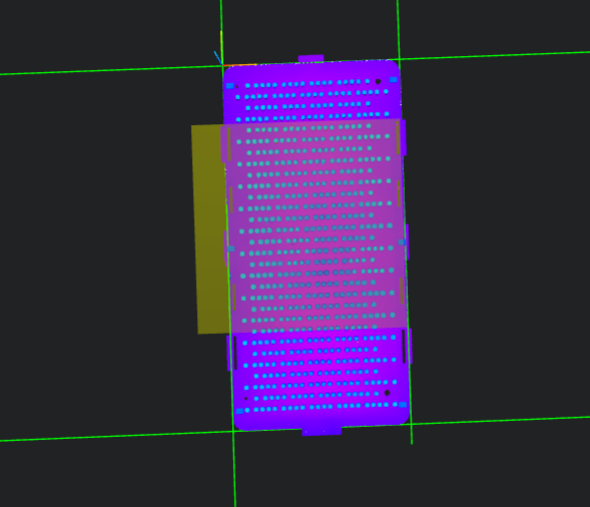
Select the
3D Geometric Intersectiontool, bind two of the four edges found in the previous step as inputs respectively, and obtain the four vertices: top-left, bottom-left, top-right, and bottom-right.Select the
Multi-Point Positioning Tool, bind the position parameters of the four vertices obtained in the previous step as input points, execute the tool to output the center point of the four vertices (top, bottom, left, and right), and adjust the point cloud position XY to the center point at the same time.
Crop Out the Region to Be Measured
This project focuses on the coplanarity of solder balls. To facilitate subsequent measurement of solder balls directly, the solder ball region can be cropped out.
Select the
3D Croppingtool, set the region box to include only the solder ball point cloud region, and output the point cloud containing only the solder ball region to IM1 for subsequent processing.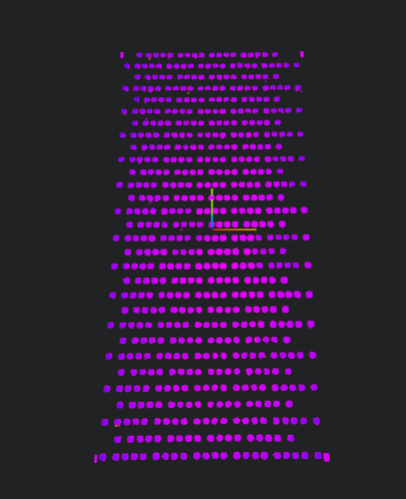
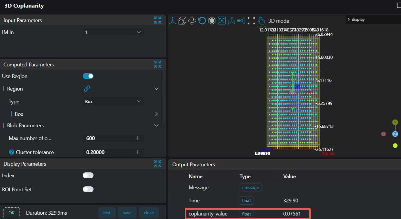
3. Coplanarity Measurement
Select the Coplanarity tool, frame the region for measurement, and perform coplanarity detection.
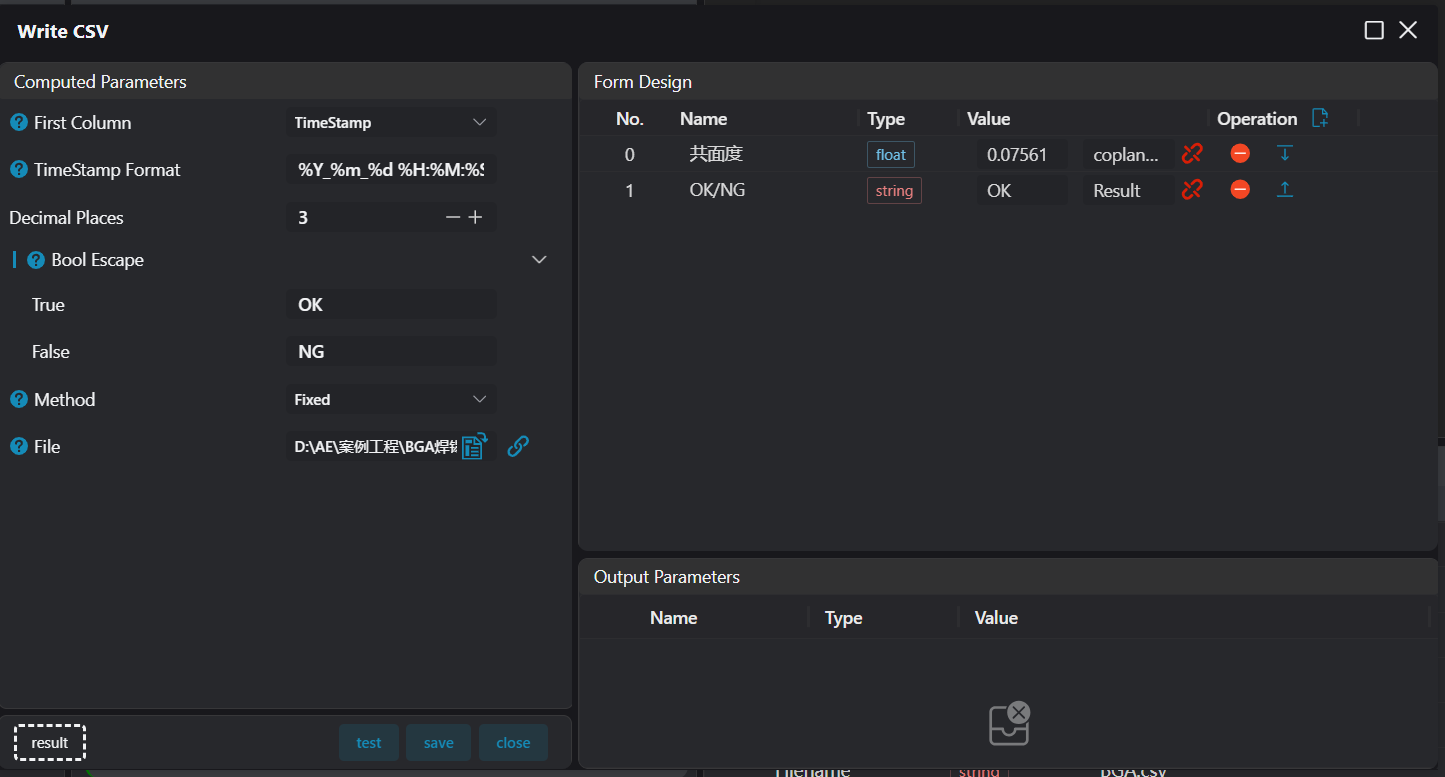
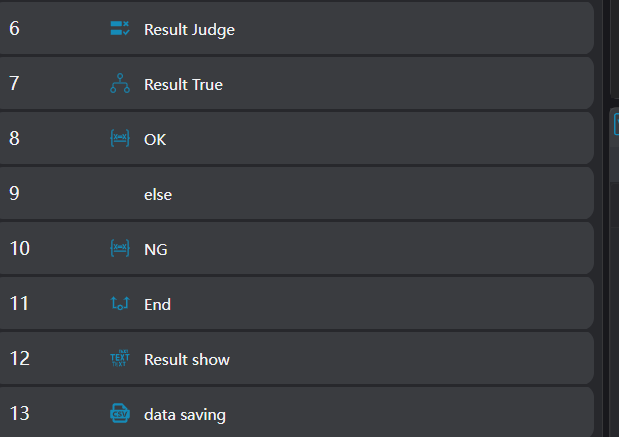
4. Data Judgment and Saving
Select the Data Check, Conditional Branch, 3D Data Display, and Variable Setting tools to judge the measurement results and display them on the image. Use the Write to CSV tool to save the judgment results and data in a file.
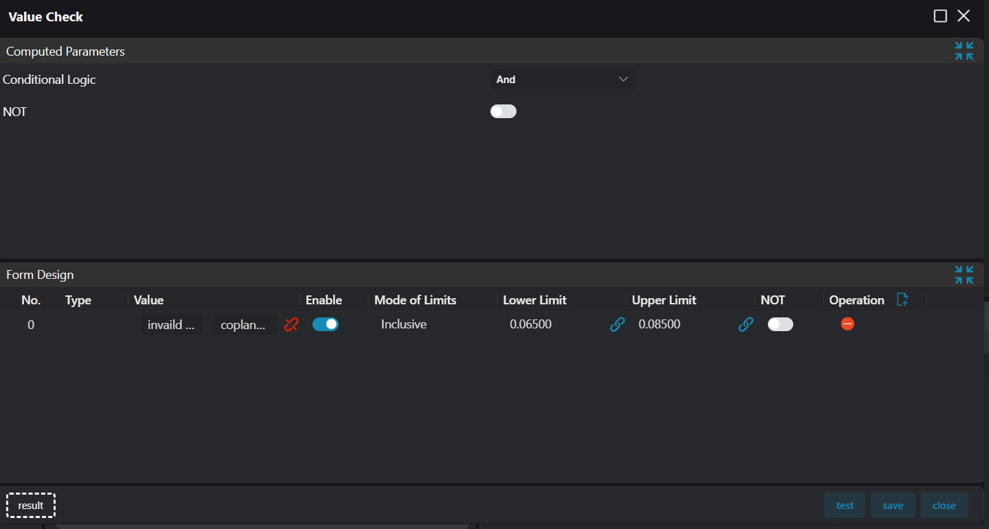
- The
Data Checkoperator binds the planarity value output by theCoplanaritytool and provides the lower and upper limit data of the judgment value.
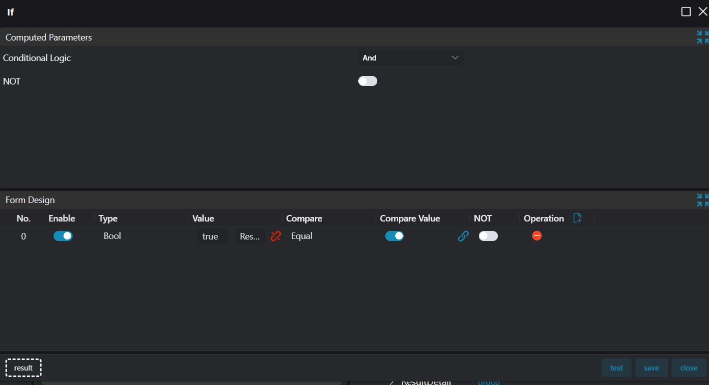
- Use the
Conditional Branchoperator to judge the overall status based on the results of theData Checkoperator.
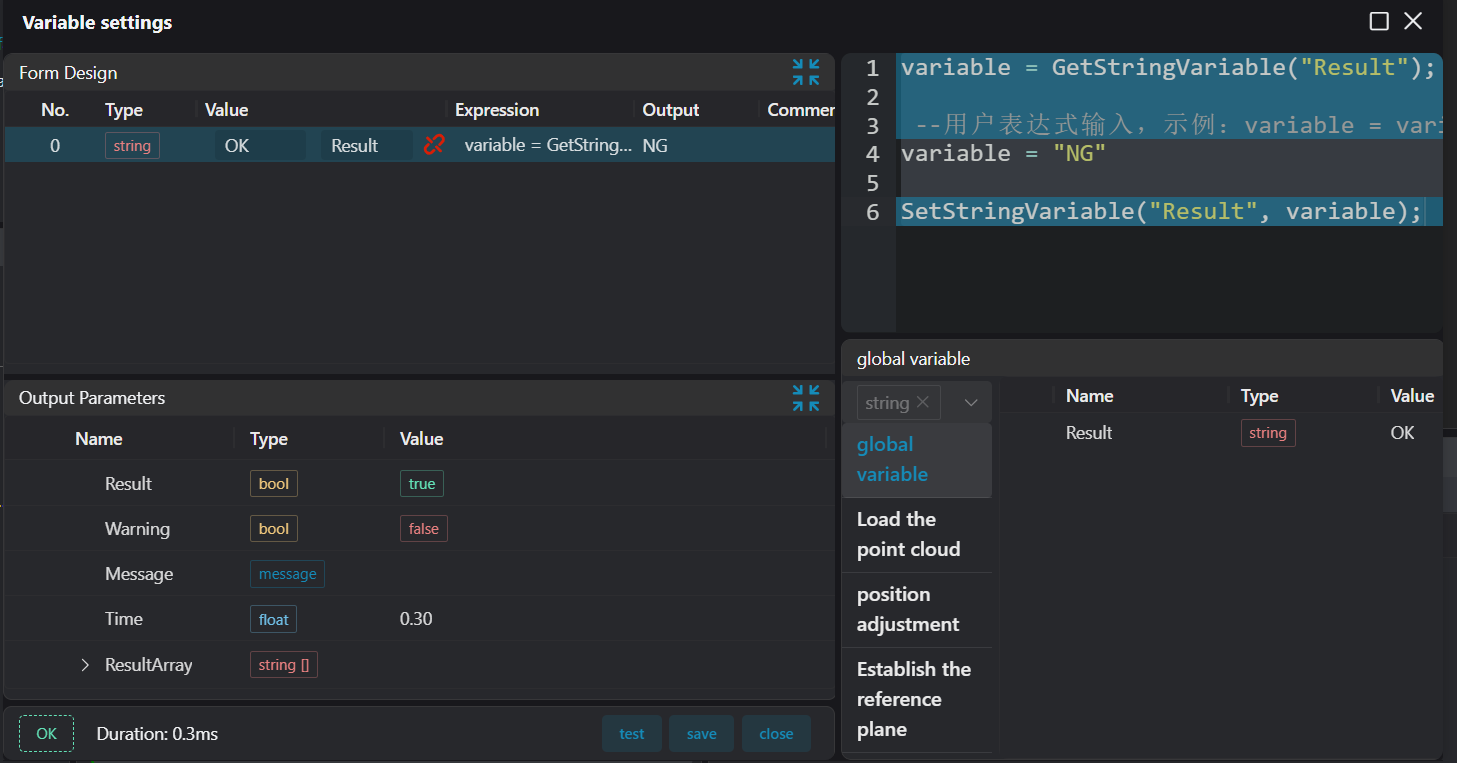
- Based on the status of the
Conditional Branchoperator, use theVariable Settingoperator to complete the overall status update.
- Use the
3D Data Displayoperator to display the results.
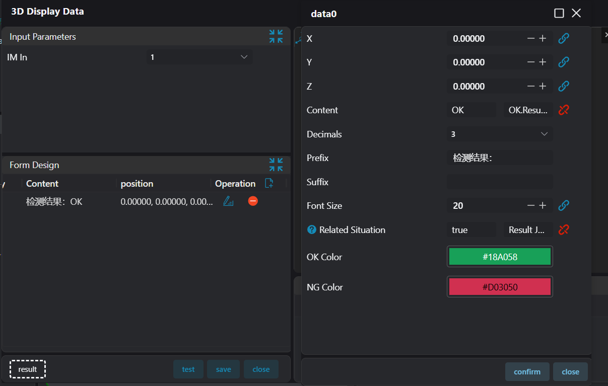
- Use the
Write to CSVoperator to bind the data of theCoplanarityoperator and the updated results to save the data.