3D Geometry Creation
Operator Function
Select the mode and input corresponding parameters to create the corresponding geometric type.
Parameter Introduction
Input Parameters

| Parameter | Range | Default Value | Description | Illustration |
|---|---|---|---|---|
| Input Image | 0-8 | 0 | IM number for image input | |
Calculation Parameters
| Parameter | Range | Default Value | Description | Illustration |
|---|---|---|---|---|
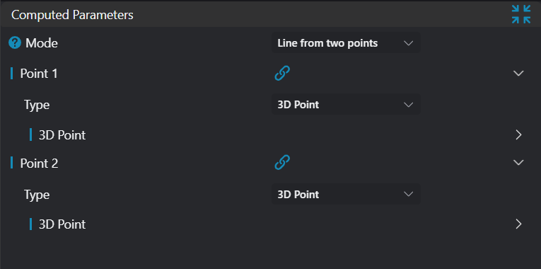
| Mode | Two Points Line: Input two points, output line parameters created by the two points Point and Line Determine Plane: Input a point and a line, output created plane parameters Three Points Determine Plane: Input three points, output created plane parameters | 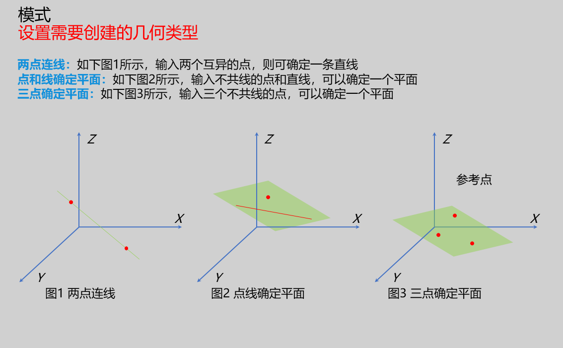 | ||
| Point 1 | Only enabled when mode is Two Points Line and Three Points Determine Plane Position: Input X, Y, Z coordinates of the point | |||
| Point 2 | Only enabled when mode is Two Points Line and Three Points Determine Plane Position: Input X, Y, Z coordinates of the point | |||
| Point 3 | Only enabled when mode is Three Points Determine Plane Position: Input X, Y, Z coordinates of the point | |||
| Point | Only enabled when mode is Point and Line Determine Plane Position: Input X, Y, Z coordinates of the point | |||
| Line | Only enabled when mode is Point and Line Determine Plane Position: Input X, Y, Z coordinates of a point on the line Direction: Input the direction vector of the line |
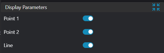
Result Display
| Parameter | Range | Default Value | Description | Illustration |
|---|---|---|---|---|
| Point | true/false | false | If enabled, display the point in the image | |
| Point 1 | true/false | false | If enabled, display Point 1 in the image | |
| Point 2 | true/false | false | If enabled, display Point 2 in the image | |
| Point 3 | true/false | false | If enabled, display Point 3 in the image | |
| Line | true/false | false | If enabled, display the line in the image | |
| Plane | true/false | false | If enabled, display the plane in the image |
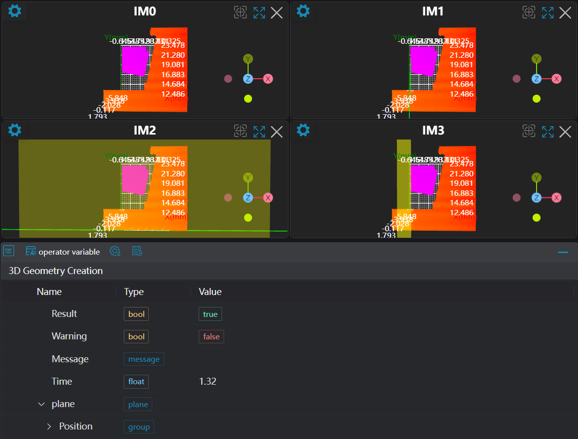
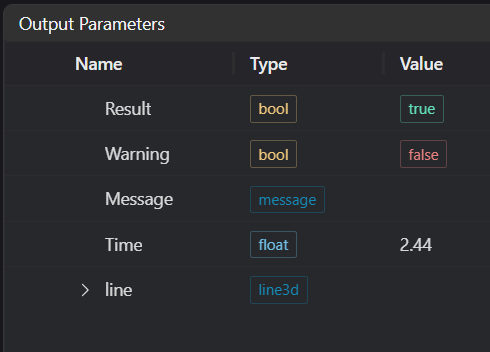
Output Parameters
| Name | Type | Range | Description |
|---|---|---|---|
| Result | bool | true/false | true for success false for failure |
| Warning | bool | true/false | true indicates a warning false indicates no warning |
| Message | string | Output success, error, or warning messages. Empty if no error or warning. | |
| Time | float | Operator execution time, unit: ms | |
| line | line3d | Output line | |
| plane | plane | Output plane |
Tip
For more detailed explanations of parameter types, please refer to Type Definitions
Exception Troubleshooting
| No. | Exception Information | Corresponding Parameter | Solution |
|---|---|---|---|
| 1 | Input Geometry 1 type is {0}, invalid geometry type | Geometry Type | Input Geometry 1 type as Point |
| 2 | Input Geometry 2 type is {0}, invalid geometry type | Geometry Type | Input Geometry 2 type as Point/3D Line |
| 3 | Input two points are the same | Modify one of the input points | |
| 4 | Input line parameters are invalid | Input line direction vector parameters cannot be all zeros | |
| 5 | Input geometry is collinear | Input three non-collinear points or a point and a line | |
| 6 | Input Geometry 3 type is {0}, invalid geometry type | Geometry Type | Input Geometry 3 type as Point |
| 7 | Input mode is {0}, invalid input mode | Mode | Input mode must be one of: Two Points Line/Three Points Determine Plane/Point and Line Determine Plane |
Example Introduction
Engineering Design
Select the
Load Point Cloudtool to load the required 3D point cloud image to IM0.Select the
3D Croptool to copy IM0 to IM1, IM2, and IM3 respectively for different operations.Select multiple
3D Square Probetools to obtain two points for Two Points Line, obtain a point and a line for Point and Line Determine Plane, and obtain three points for Three Points Determine Plane.Select the
3D Geometry Creationtool.
Tool Usage
Select the input image for the operation. The image number must match the IM number where the image is located in the project.
Set inputs
Set different modes, bind the points or lines obtained from the previous step's square probe tools as inputs.
Set the parameters.
Check the content you want to display in the result display section.
Click
Testto check if the image window and parameters meet expectations.If there are no issues, click
Save. Run the operator in the run list, and then view the running results in the corresponding IM.