3D Flatness
Operator Function
Using the average point method, calculate an average point in each region, and use these average points to fit a reference plane. Calculate the peak-to-reference flatness deviation and reference-to-valley flatness deviation. The final flatness = peak-to-reference flatness deviation - reference-to-valley flatness deviation.
Parameter Introduction
Input Parameters

| Parameter | Range | Default Value | Description | Illustration |
|---|---|---|---|---|
| Input Image | 0-8 | 0 | IM number for image input | |
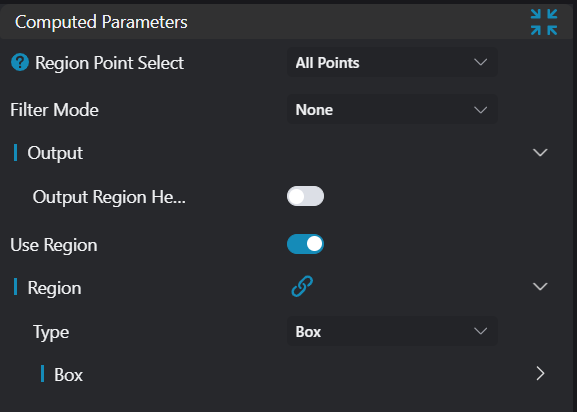
Calculation Parameters
| Parameter | Range | Default Value | Description | Image |
|---|---|---|---|---|
| Region Point Selection | All Points/Average Point | All Points | See Region Point Selection | 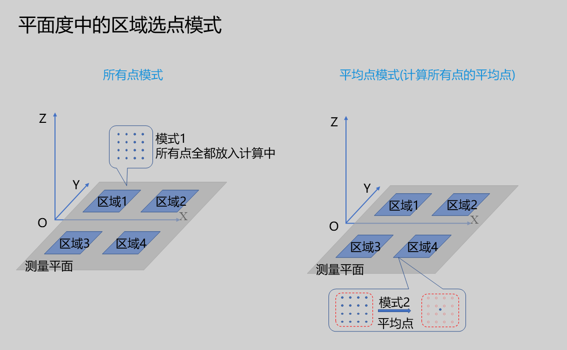 |
| Number of Regions | 1 | Set the number of detection regions. For Average Point mode, at least 4 ROI regions must be set and the regions cannot be collinear. | ||
| Filter Method | None/Percentile Filter | None | None: Do not use any filtering method Percentile Filter: Use percentile filtering method to filter points in each region and remove outliers. See Percentile Filter |
Region Point Selection
Currently, two point selection methods are provided: All Points and Average Point modes.
| Parameter | Range | Default Value | Description | Image |
|---|---|---|---|---|
| All Points | In this mode, all points in the ROI participate in flatness calculation. | | ||
| Average Point | In this mode, the average point of all points in each region is calculated, and then the average point is included in the calculation. | |
Note: The average point flatness calculation method, on one hand, preserves the statistical information of all points in the region, to some extent suppressing the influence of noise points, making the calculation results more stable; on the other hand, since only
average pointsare used for calculation, it is also faster. However, if using theAverage Pointmode, at least4ROI regions must be set and the regions cannot becollinear.
Percentile Filter Mode
If enabled, percentile filtering will be performed on points in each region.
| Parameter | Range | Default Value | Description | Image |
|---|---|---|---|---|
| Low Percentage | Calculate the low threshold in the Z direction based on the input percentage, removing all points below this threshold | 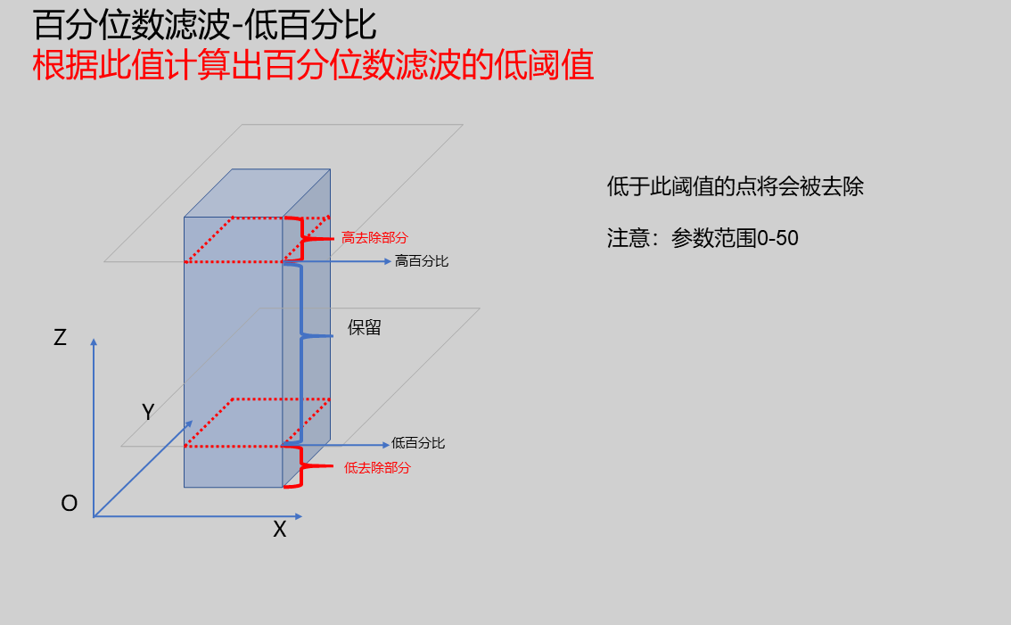 | ||
| High Percentage | Calculate the high threshold in the Z direction based on the input percentage, removing all points above this threshold |  |
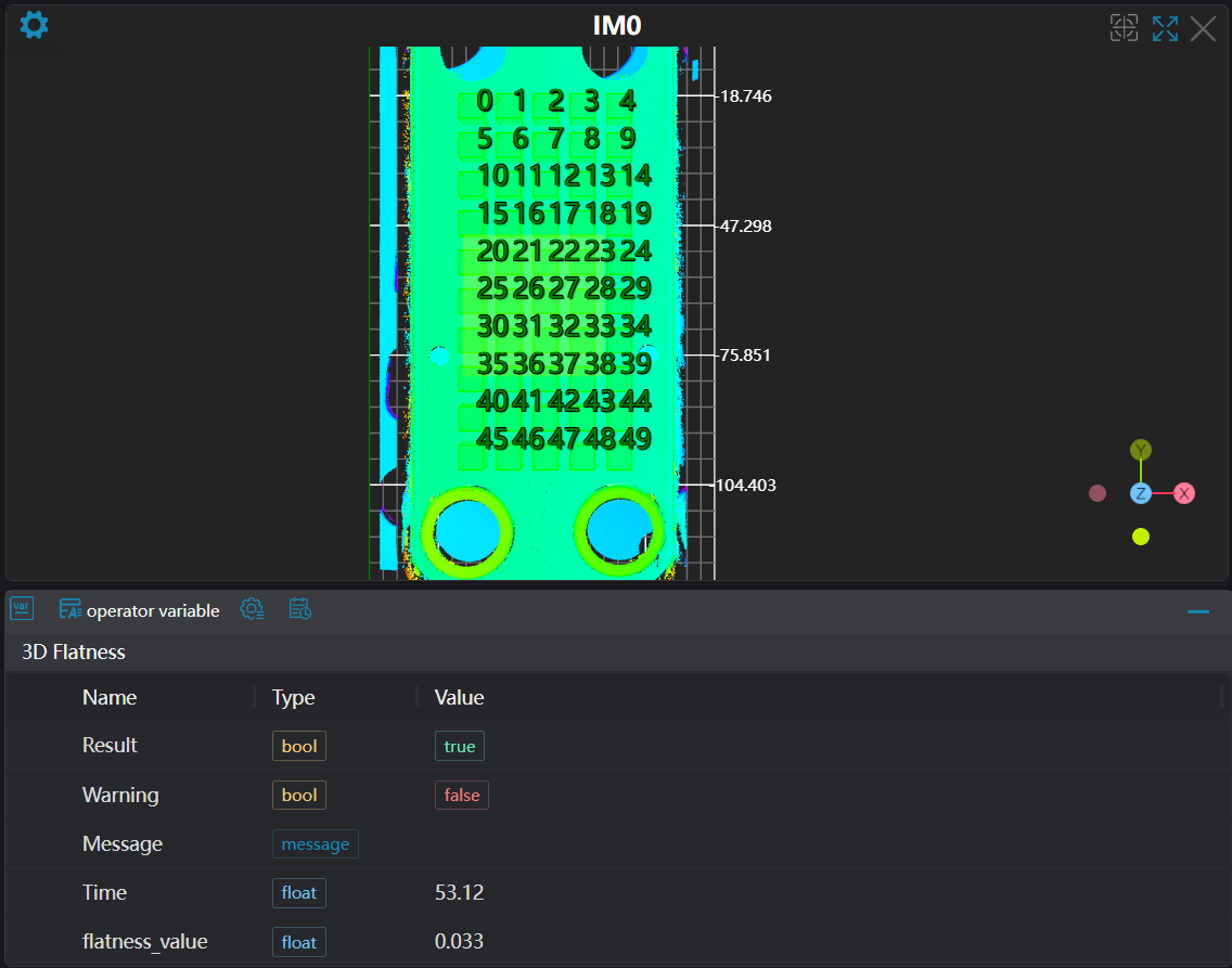
Result Display
| Parameter | Range | Default Value | Description | Illustration |
|---|---|---|---|---|
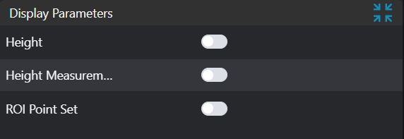
| Height | true/false | false | Region height value. If enabled, display in the image | |
| Height Measurement Points | true/false | false | Height position points. If enabled, display in the image | |
| ROI Point Set | true/false | false | Region point set selected by ROI box. If enabled, display in the image |
Output Parameters
| Name | Type | Range | Description |
|---|---|---|---|
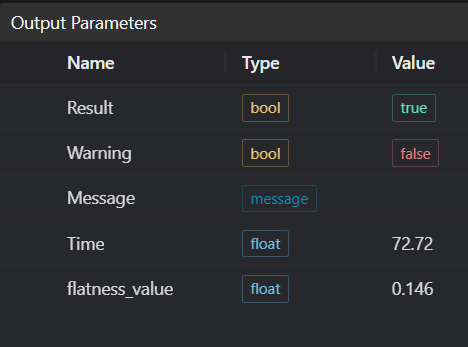
| Result | bool | true/false | true for success false for failure |
| Warning | bool | true/false | true indicates a warning false indicates no warning |
| Message | string | Output success, error, or warning messages | |
| Time | float | Operator execution time, unit: ms | |
| region_height | float[] | Region height array | |
| flatness_value | float | Flatness value |
Exception Troubleshooting
| No. | Exception Information | Corresponding Parameter | Solution |
|---|---|---|---|
| 1 | High and low percentages cannot both be 50.0 | Adjust high and low percentages, cannot both be 50 | |
| 2 | Input value is {0}, invalid height statistics method | Height Mode | Only Minimum, Maximum, Mean, Median supported |
| 3 | Global flatness test failed | 1. Check if input point cloud is empty 2. Check if high and low percentages are both greater than 0 and less than 50 | |
| 4 | At least 4 regions need to be set in this mode | Select at least 4 different regions, and the center points of the regions should not be on a straight line | |
| 6 | Input value is {0}, invalid region point selection method | Region Point Selection | Only All Points, Single Average Point supported |
Example Introduction
Engineering Design
- Select the
3D Load Point Cloudtool. - Select 2
Call Programtools to perform position adjustment and plane fitting respectively. - Select 2
3D Flatnesstools, using Average Point mode and All Points mode respectively.
Tool Usage
Select the IM number of the input image.
Set the parameters.
Click
Testto check if the image window and parameters meet expectations.If there are no issues, click
Save. Run the operator in the run list, and then view the running results in the corresponding IM.