3D Contour Intersection
Operator Function
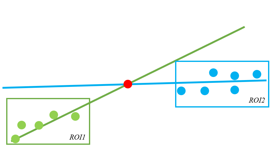
On the contour image, extract two straight lines respectively. If the two lines intersect, output the intersection point coordinates. If the two lines are parallel, an error is reported.
Parameter Introduction
Input Parameters

| Parameter | Range | Default Value | Description | Illustration |
|---|---|---|---|---|
| Input Image | 0-8 | 0 | The IM number for image input | |
Calculation Parameters
| Parameter | Range | Default Value | Description | Illustration |
|---|---|---|---|---|
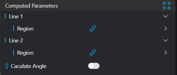
| Region | Only enabled when acquisition method is line fitting; fit line based on points within the region | |||
| Type | 1D Window | 1D Window | Only enabled in manual mode; set manually selected type: 1D Window | |
| Start Point | Only enabled in manual mode; input X, Z coordinates of start point | |||
| End Point | Only enabled in manual mode; input X, Z coordinates of end point | |||
| Calculate Angle | If enabled, calculate the angle between lines |
Result Display
| Parameter | Range | Default Value | Description | Illustration |
|---|---|---|---|---|
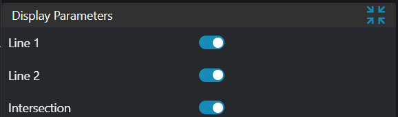
| Line 1 | true/false | false | If enabled, display Line 1 in the image | |
| Line 2 | true/false | false | If enabled, display Line 2 in the image | |
| Intersection Point | true/false | false | If enabled, display the intersection point of two lines in the image | |
| Angle | true/false | false | If enabled, display the angle between two lines in the image |
Output Parameters
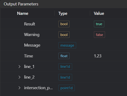
| Name | Type | Range | Description |
|---|---|---|---|
| Result | bool | true/false | true for success false for failure |
| Warning | bool | true/false | true indicates there is a warning false indicates there is none |
| Message | string | Outputs success, error, or warning information; if there is no error or warning, it is empty | |
| Time | float | Operator execution time, unit: ms | |
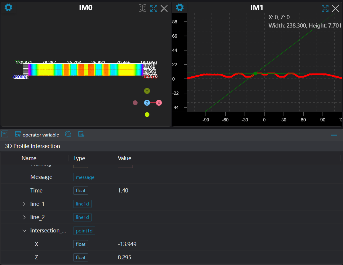
| intersection_point | point1d | Output intersection point |
Tip
For more detailed explanations of parameter types, please refer to Type Definitions
Exception Troubleshooting
| No. | Exception Information | Corresponding Parameter | Solution |
|---|---|---|---|
| 1 | Failed to get feature points in crop region | Adjust start and end parameters of point acquisition region to ensure valid points exist in selected area | |
| 2 | Input region type is {0}, invalid region type | Region Type | Input region type must be 1D Window |
| 3 | Error getting region for Line 1 | Adjust start and end parameters of Line 1 acquisition region to ensure at least two valid points exist in selected area | |
| 4 | Error getting region for Line 2 | Adjust start and end parameters of Line 2 acquisition region to ensure at least two valid points exist in selected area | |
| 5 | Two lines are parallel | - | - |
Example Introduction
Engineering Design
Select the
Load Point Cloudtool to load the 3D point cloud image to be processed into IM0.Select the
3D Contour Extractiontool to extract contours into IM1, IM2, IM3 respectively.Select the
3D Contour Intersectiontool.
Tool Usage
Select the input image for operation; the image number must match the IM number where the image is located in the project.
Move the window to the position where line fitting is needed, enclosing the area where line fitting is required.
Usage Tips
- Use the ROI controller on the image window to drag or scale the window;
- Directly modify the start or end coordinates of the window in the calculation parameters to adjust the window position and size;
Check the content you want to display in the result display section
Click
Testto check if the image window and parameters meet expectationsIf there are no issues, click
Save, then run the operator in the run list to view the results in the corresponding IM