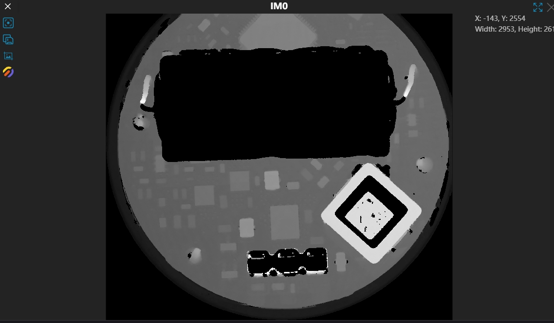
Image Display Panel

Image Operations
 These tools are located in the software toolbar
| Icon | Name | Description |
|---|---|---|
 | Add View | Adds an Image Display (IM) window. Different IM windows can display corresponding image content. |
 | Reset Window Layout | IM window sizes can be edited. Click this to restore them to their original sizes. |
 | Save Layout | Saves the current layout of the IM windows.With multiple IM windows, the system uses automatic layout by default. Users can manually drag individual window sizes and positions. |
 | Image Operation Instructions | View the operation instructions for the IM window. |
2D Image Tools
Tool List
| Icon | Name | Description |
|---|---|---|
 | Center | Centers the entire image in the image window. |
 | Save Image | Saves the original image from this IM. Formats include png, bmp, jpg, tiff. |
 | Save Screenshot | Saves a screenshot of the current image in the IM. Format is png. |
 | Render Settings | Sets the pseudo-color rendering for depth maps. |
3D Image Tools
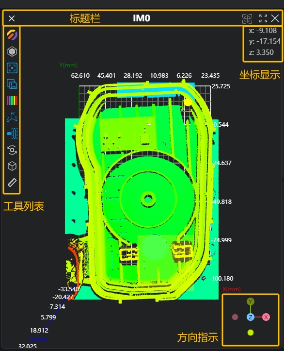
Title Bar
| Icon | Name | Description |
|---|---|---|
 | Settings | Modifies the image display. |
| IM0 | Window Name | The window name is fixed, ranging from IM0 to IM8. |
 | Auto Center (On/Off) | When enabled, the image automatically centers after refreshing. |
 | Full Screen (On/Off) | When enabled, the window expands to full screen. |
 | Close Window | Closes the window; the image window no longer displays this IM.Note: IM0 cannot be closed. |
Tool List
| Icon | Name | Description |
|---|---|---|
| Render Settings | Sets the point cloud rendering parameters. | |
| Color Rendering | Height: Displays in uniform color based on the point cloud's Z-axis range. White: Displays the point cloud in pure white. Grayscale: Displays in uniform grayscale (0-255) based on the Z-axis range. Mixed: Blends the height color with the point cloud's original color. Original Color: The point cloud's original color, usually obtained directly from the camera. Point clouds processed by image tools will lose their original color.This setting is only adjustable in Point Cloud mode. | |
 | Render Mode | Point Cloud: Displays as points. Mesh: Connects adjacent points with triangles to form a mesh. Surface: Displays the mesh as surfaces. |
| Render Values | Value: Decrease when point spacing is small, increase when point spacing is large. Brightness: Adjusts the display brightness. This setting is only adjustable in Mesh and Surface modes. | |
 | Bounding Box (On/Off) | Controls the display of the point cloud's bounding box. |
| Center | Centers the entire point cloud in the image window. |
| Save Point Cloud | Saves the point cloud from this IM. Formats include pcd, ply, txt, csv. |
 | Point Cloud Color Settings | Modifies the color rendering range of the point cloud. |
 | Point Cloud Color Settings | Auto: Automatically calculates the rendering range based on the point cloud's Z-axis range. Min Value: Manually sets the minimum Z value. Points below this value appear gray. Max Value: Manually sets the maximum Z value. Points above this value appear gray. |
 | Coordinate Axes (On/Off) | Controls the display of coordinate axes in the image window. |
 —— —— | Perspective Camera —— Orthographic Camera | Perspective Camera: Field of view is conical, creating a perspective effect where closer objects appear larger. —— Orthographic Camera: Field of view is rectangular, objects appear the same size regardless of distance. |
 | Auto Rotate (On/Off) | When enabled, the point cloud rotates around the origin at a fixed speed. |
 | OBB (On/Off) | Turns the point cloud's Oriented Bounding Box on or off. |
 | Point-to-Point Distance (On/Off) | When enabled, users can select two points on the point cloud with the mouse to measure the distance.Selection method: Ctrl + Left Mouse Button |
Coordinate Display
| Icon | Name | Description |
|---|---|---|
 | Coordinate Display | Shows the coordinate values of the point under the mouse cursor as it moves over the point cloud. |
Orientation Indicator
| Icon | Name | Description |
|---|---|---|
 | Orientation Indicator | Indicates the current viewing direction of the point cloud. Click any axis label (X, Y, Z, -X, -Y, -Z) to align the view to that axis. |