3D Display
Operator Function
Select the objects to be drawn and input corresponding parameters to display the corresponding geometric shapes.
Parameter Introduction
Input Parameters

| Parameter | Range | Default Value | Description | Illustration |
|---|---|---|---|---|
| Input Image | 0-8 | 0 | The IM number for image input | |
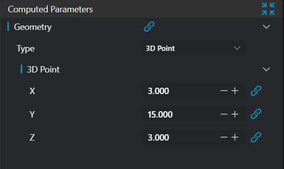
Calculation Parameters
| Parameter | Range | Default Value | Description | Illustration |
|---|---|---|---|---|
| Type | 3D Point/3D Line/Plane/2D Window/Box/Cylinder | 3D Point | Input point coordinates Input a point on the line and direction vector Input a point on the plane and normal vector Input X, Y coordinates of opposite corners of a square window to display it on the image Input box diagonal coordinates Input cylinder top and bottom circle centers and radius |
Tip
For more detailed explanations of parameter types, please refer to Type Definitions
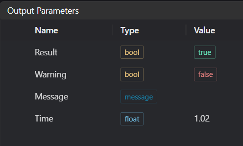
Output Parameters
| Name | Type | Range | Description |
|---|---|---|---|
| Result | bool | true/false | true for success false for failure |
| Warning | bool | true/false | true indicates there is a warning false indicates there is none |
| Message | string | Outputs success, error, or warning information; if there is no error or warning, it is empty | |
| Time | float | Operator execution time, unit: ms |
Exception Troubleshooting
| No. | Exception Information | Corresponding Parameter | Solution |
|---|---|---|---|
| 1 | Invalid line parameters | Input line direction vector parameters cannot all be 0 | |
| 2 | Invalid plane parameters | Input plane normal vector parameters cannot all be 0 | |
| 3 | Invalid square window parameters | Input window start and end points must be different | |
| 4 | Invalid box parameters | Input box start and end points must be different and same parameters cannot be identical | |
| 5 | Invalid cylinder parameters | Cylinder radius must be > 0, height must be > 0 | |
| 6 | Input geometry type is {0}, invalid geometry type | Geometry Type | Input target type must be Line/Plane/Square Window/Point/Box/Cylinder |
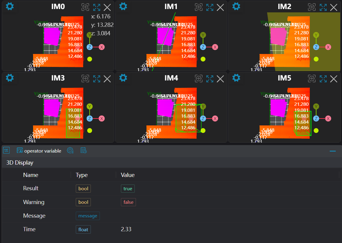
Example Introduction
Engineering Design
Select the
Load Point Cloudtool to load the 3D point cloud image to be processed into IM0.Select the
3D Croptool, copy IM0 to IM1, IM2, IM3, IM4, IM5 respectively.Select six
3D Displaytools to display different geometries (Point, Line, Plane, Window, Cylinder, Box).
Tool Usage
Select the input image for operation; the image number must match the IM number where the image is located in the project.
Set input points or lines:
If it's a point or fitted line, set the window position to get points or lines; if it's a baseline, set the baseline value.
Set parameters
Check the content you want to display in the result display section
Click
Testto check if the image window and parameters meet expectationsIf there are no issues, click
Save, then run the operator in the run list to view the results in the corresponding IM