3D Position Adjustment
Operator Function
Adjust the position of the point cloud by performing translation or rotation operations based on input position information.
Parameter Introduction
Input Parameters

| Parameter | Range | Default Value | Description | Illustration |
|---|---|---|---|---|
| Input Image | 0-8 | 0 | IM number for image input | |
Calculation Parameters
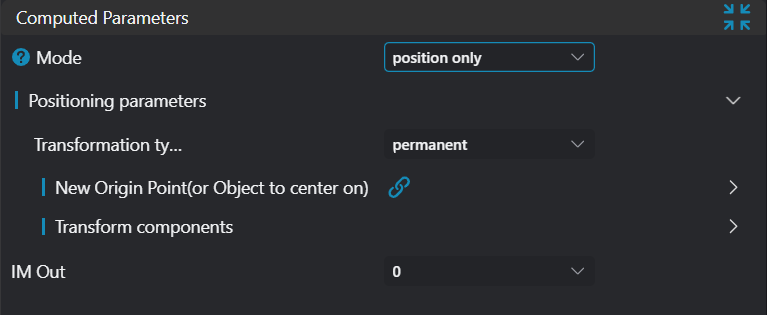
Position Only Adjustment Parameters
| Parameter | Range | Default Value | Description | Illustration |
|---|---|---|---|---|
| Mode | Position Only: Perform coordinate transformation on the input point cloud based on the input New Origin information Orientation Adjustment: Adjust the orientation and position of the point cloud based on the input New Direction information | 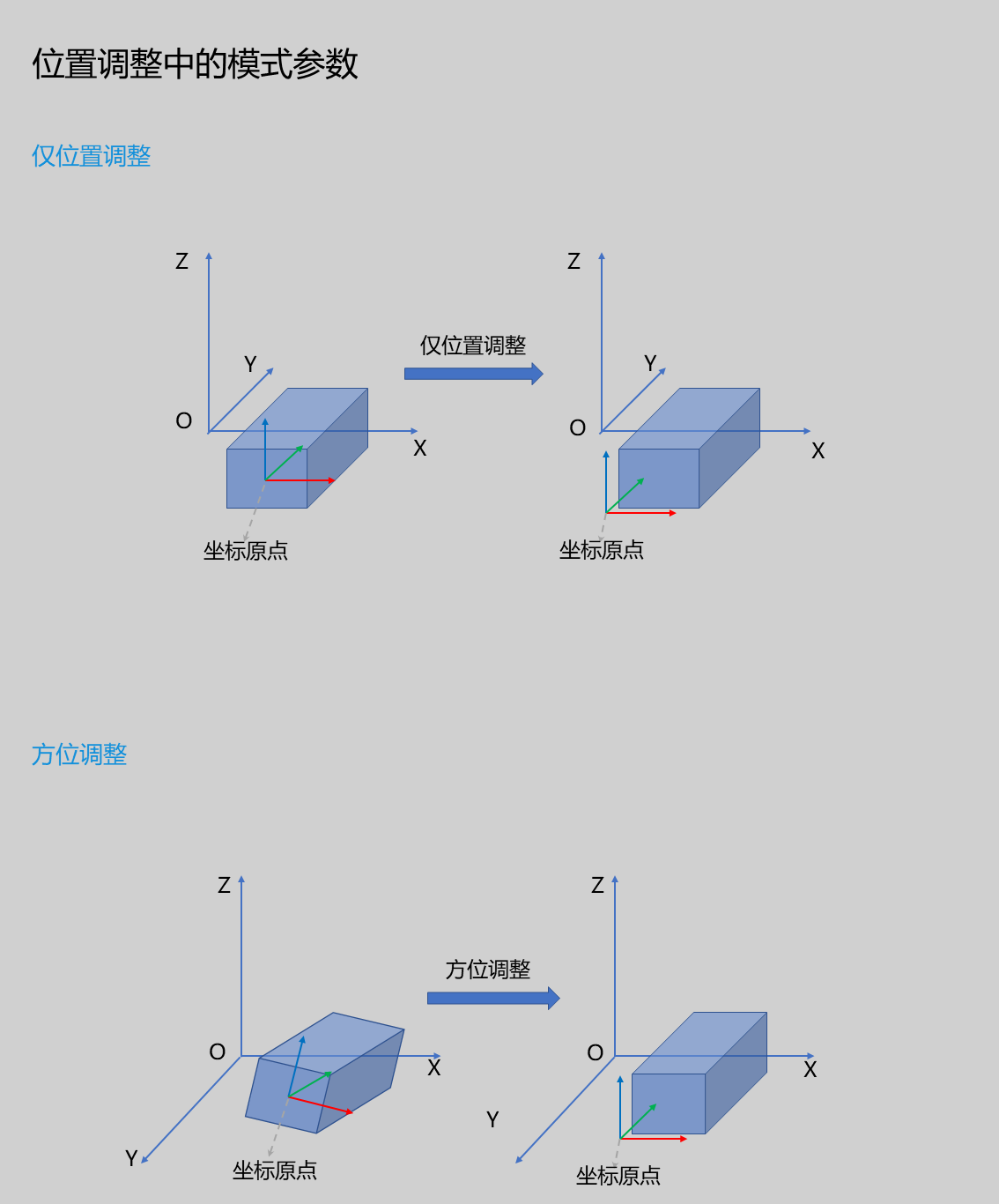 | ||
| Transformation Type | Permanent: Output the transformed point cloud Temporary: Output the transformation matrix Note: Temporary mode currently does not output the transformation matrix to registers and does not transform the original point cloud. Therefore, when setting up, the transformation type needs to be selected as Permanent. Temporary mode will be gradually introduced in future versions. | |||
| Type | Line: Use the line's position information (center point of the line) as the origin 3D Plane: Use the plane's position information (center point of the plane) as the origin Box: Calculate the center point from the box's start and end points, and use it as the origin | |||
| Transformation Component | Adjust X Position: Only adjust the X coordinate of the new origin to 0 Adjust Y Position: Only adjust the Y coordinate of the new origin to 0 Adjust Z Position: Only adjust the Z coordinate of the new origin to 0 | |||
| Output Image | IM number for image output |
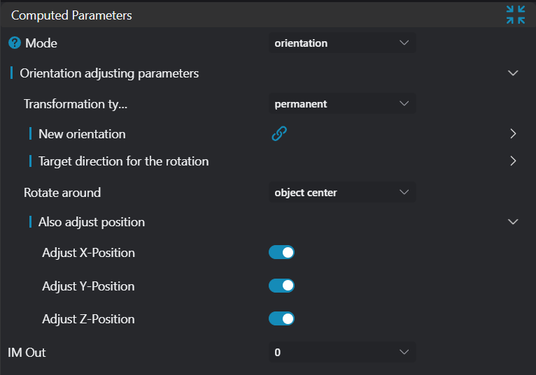
Orientation Adjustment Parameters
| Parameter | Range | Default Value | Description | Illustration |
|---|---|---|---|---|
| Mode | Position Only/Orientation Adjustment | Orientation Adjustment | Position Only: Perform coordinate transformation on the input point cloud based on the input New Origin information Orientation Adjustment: Adjust the orientation and position of the point cloud based on the input New Direction information | 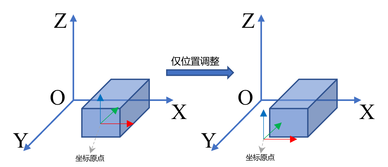 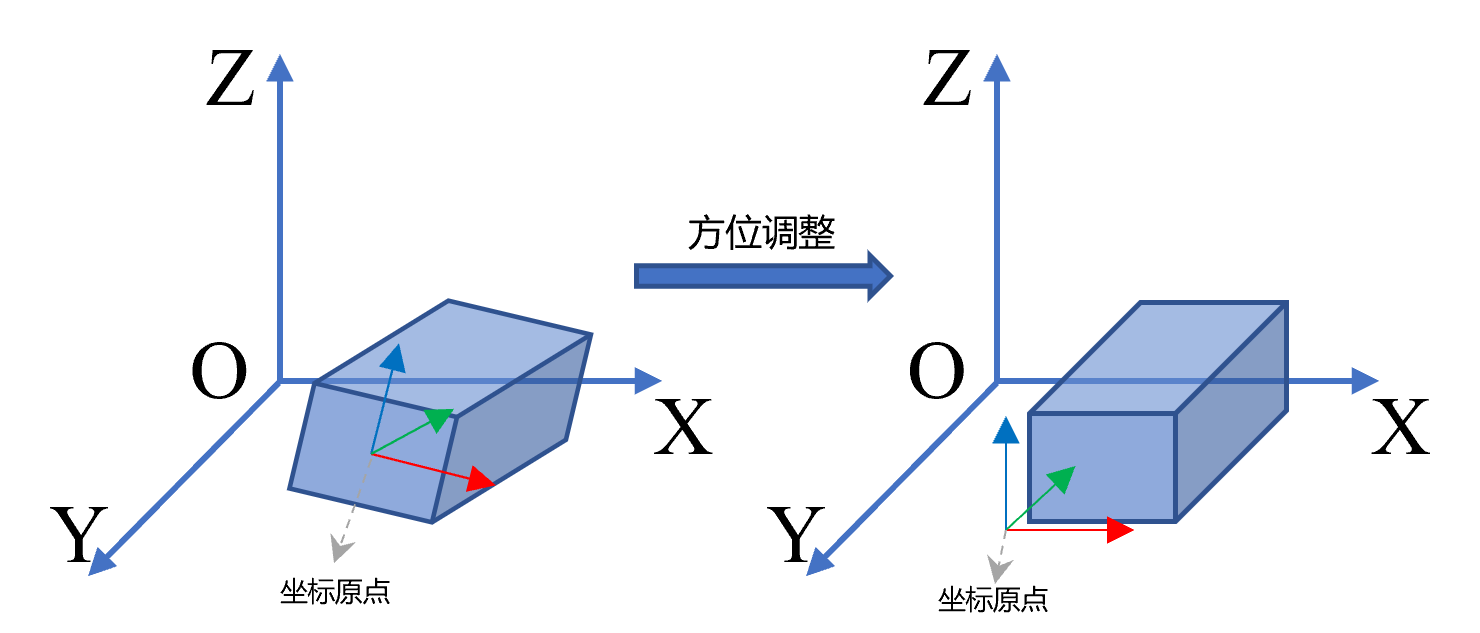 |
| Transformation Type | Permanent: Output the transformed point cloud Temporary: Output the transformation matrix | |||
| Type | 3D Line/3D Plane | 3D Line | 3D Line: Use the line's direction vector as the new direction 3D Plane: Use the plane's normal vector as the new direction | |
| Rotate Vector to Axis | +X/-X/+Y/-Y | +X | +X: Target direction vector is the +X direction of the coordinate axis +Y: Target direction vector is the +Y direction of the coordinate axis -X: Target direction vector is the -X direction of the coordinate axis -Y: Target direction vector is the -Y direction of the coordinate axis | |
| Angle Range | 360 degrees/180 degrees | 360 degrees | 360 degrees: Use [0°, 360°] angle range when calculating new direction and target direction 180 degrees: Use [0°, 180°] angle range when calculating new direction and target direction | |
| Rotation Center | Target Center/Origin (0,0,0)/ | Target Center | Target Center: Rotate around the position center of the new direction type Origin (0,0,0): Rotate around the Z-axis Specific Position: Set a custom rotation center | |
| Simultaneously Adjust Position | Adjust X Position: Only adjust the X coordinate of the new origin to 0 Adjust Y Position: Only adjust the Y coordinate of the new origin to 0 Adjust Z Position: Only adjust the Z coordinate of the new origin to 0 | |||
| Output Image | 0-8 | 0 | IM number for image output |
Tip
For more detailed explanations of parameter types, please refer to Type Definitions
Output Parameters
| Name | Type | Range | Description |
|---|---|---|---|
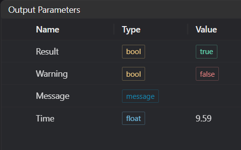
| Result | bool | true/false | true for success false for failure |
| Warning | bool | true/false | true indicates a warning false indicates no warning |
| Message | string | Output success, error, or warning messages. Empty if no error or warning. | |
| Time | float | Operator execution time, unit: ms |
Exception Troubleshooting
| No. | Exception Information | Corresponding Parameter | Solution |
|---|---|---|---|
| 1 | Input value is {0}, invalid transformation type | Transformation Type | Only permanent supported |
| 2 | Input value is {0}, invalid new origin type | New Origin Type | Only point3d, line3d, plane, Box supported |
| 3 | Input value is {0}, invalid new direction type | New Direction Type | Only line3d, plane supported |
| 4 | Input value is {0}, invalid target axis | Rotate Vector to Axis | Only +X, +Y, -X, -Y supported |
| 5 | Input value is {0}, invalid angle range | Angle Range | Only 360 degrees, 180 degrees supported |
| 6 | Input value is {0}, invalid specific position type | Only point3d, line3d, plane supported | |
| 7 | Orientation adjustment failed | 1. Check if input point cloud is empty 2. Check if new direction source is supported, only line3d, plane supported | |
| 8 | Input value is {0}, invalid position adjustment mode | Mode | Only position only, orientation supported |
| 9 | Input value is {0}, invalid rotation point type | Rotation Point Type Source | Only object center, origin, specific position supported |
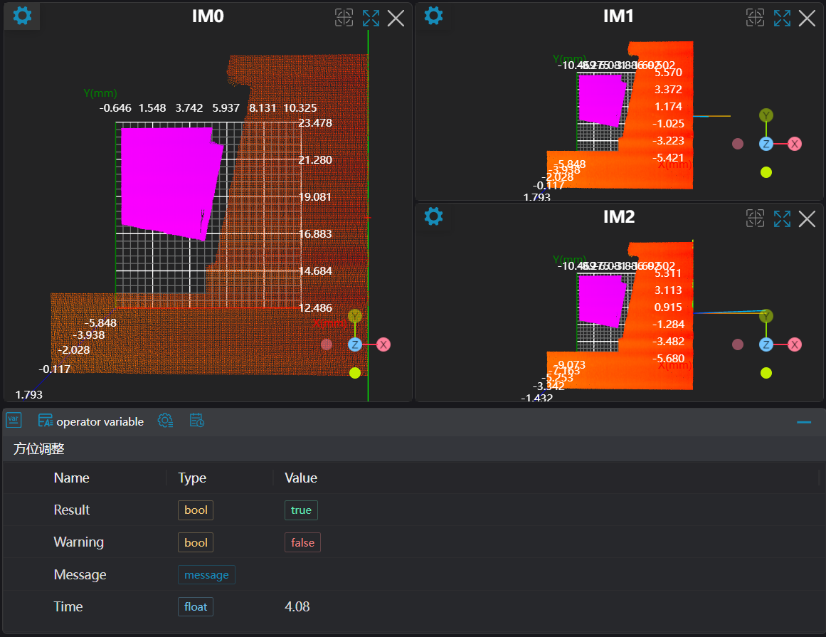
Example Introduction
Engineering Design
Select the
Load 3D Point Cloudtool to load the required 3D point cloud image to IM0.Select two
3D Square Probetools to extract contours to IM1, IM2, and obtain points and lines from IM.Select two
3D Position Adjustmenttools, setting the modes to Position Only and Orientation Adjustment respectively.
Tool Usage
Select the input image for the operation. The image number must match the IM number where the image is located in the project.
Set the parameters.
Click
Testto check if the image window and parameters meet expectations.If there are no issues, click
Save. Run the operator in the run list, and then view the running results in the corresponding IM.