Glue Path Detection
Project Overview
Project Background
Accurately measure the step difference of pins to promptly identify and eliminate defective products, thereby reducing the defect rate.
Camera Selection
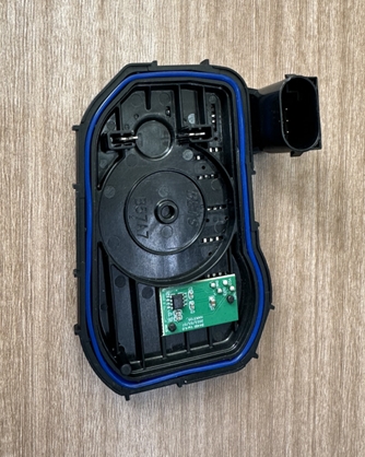
LMI Laser Line Scan Camera Gocator 2530
Detection Requirements
Height Accuracy ≤ 0.01mm
Width Accuracy ≤ 0.02mm
Measurement Cycle ≤ 4s
Solution
AI-Vision loads a glue-free template, performs template matching after image capture to extract the glue path part, and uses the glue path detection algorithm to directly detect the height and width values of the glue strip and determine whether the glue path is broken.
Design Concept
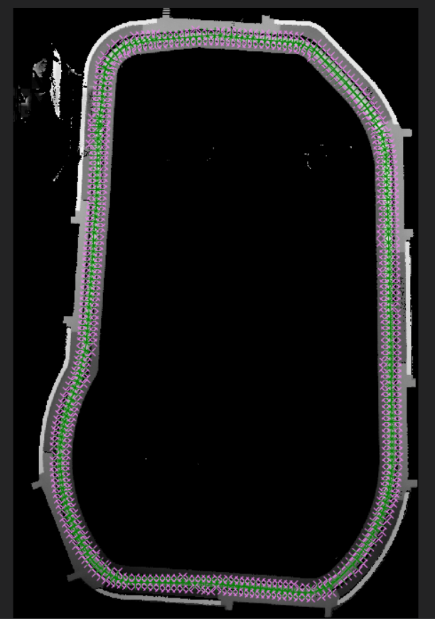
Execution Effect Display
Project Result Display:
Project Process
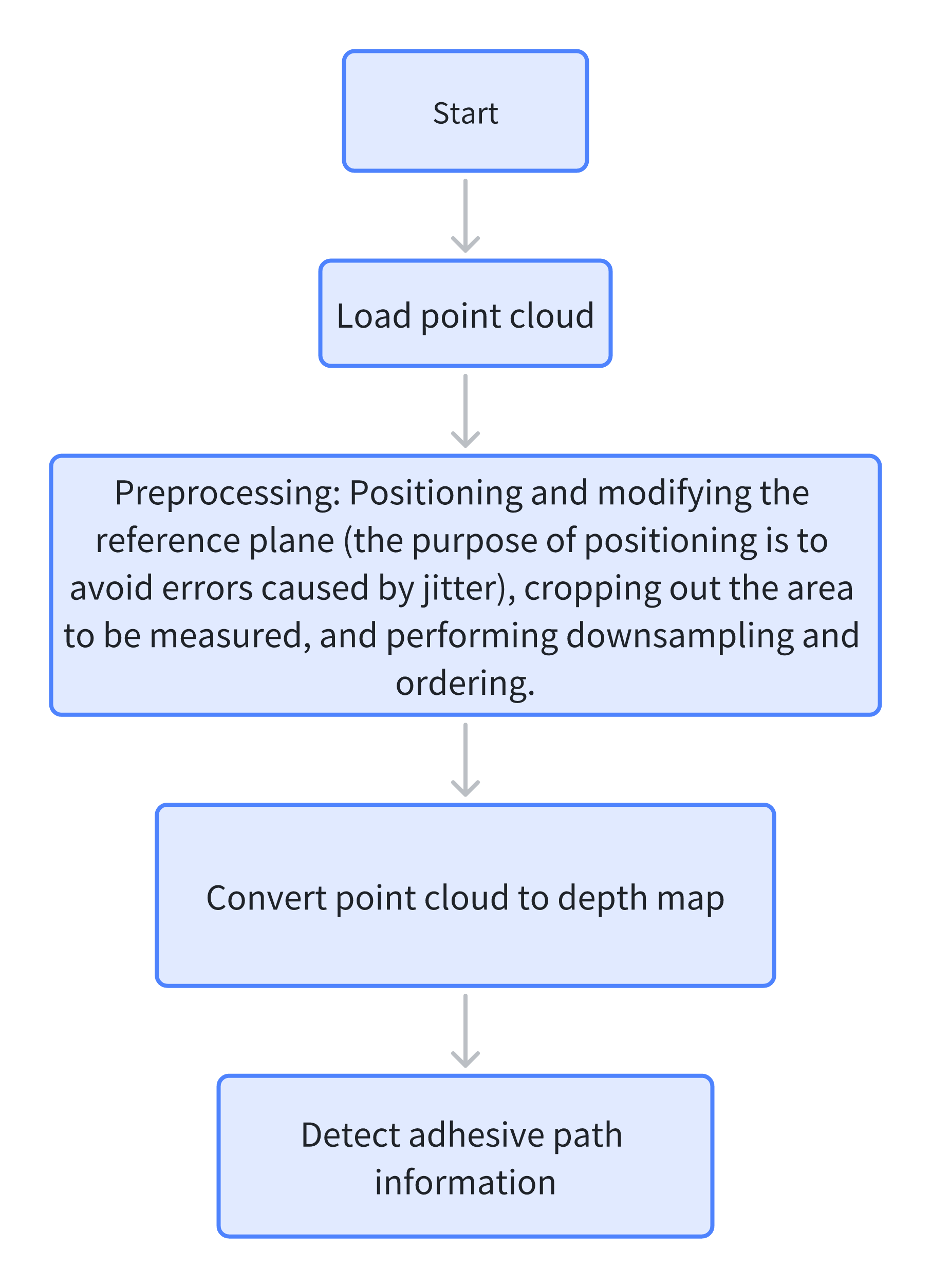
1. Initialization
Select the Load Point Cloud tool to acquire the point cloud.
2. Preprocessing
- Select the
Add 3D Square Probetool, frame the protruding part to obtain the center point coordinates and output them. - Select the
3D Position Adjustment Toolto adjust the x and y positions of the point cloud according to the output center point coordinates. - Select the
Create ROItool to frame the base area for plane fitting. - Select the
3D Planetool, bind the ROI fitted plane output by the created ROI area, and adjust the point cloud to the zero plane. - Select the
3D Clippingtool to clip the point cloud near the glue strip. - Select the
3D Downsamplingtool to downsample the point cloud and reduce the data volume of the point cloud. - Select the
3D Point Cloud Orderingtool to order the point cloud; the reason for ordering is that theGlue Path Detection - Trajectoryoperator requires ordered point cloud input.
3. Glue Path Detection
- Select the
Point Cloud to Depth Maptool to convert the ordered point cloud into a depth map. - Select the
Glue Path Detection - Trajectorytool, select the glue path trajectory on the depth map, detect the width and height of the glue strip as well as whether it is broken, and output the results.