Backplate Assembly Inspection
Project Background
Inspection Background
With the increasing demands for battery safety and reliability in industries such as new energy vehicles, energy storage systems, and consumer electronics, the manufacturing precision and assembly quality of battery casings have become key factors affecting product performance. As the core structural component of a battery pack, the stud positioning, regional flatness, and sealant path quality on the battery casing surface are directly related to the overall structural sealing, shock resistance, and long-term stability. Any minor deviation, such as stud tilt, flatness exceeding tolerance, or sealant path defects, can lead to assembly failure, poor sealing, or even safety hazards.
To meet the high-precision, high-efficiency quality control requirements, there is an urgent need to develop an automated full-size inspection system for the surface features of battery casings. This system needs to accurately measure stud tilt, small-area flatness, and inspect the completeness of the peripheral sealant path, ensuring that every key feature meets strict process standards, thereby improving product yield and ensuring the long-term reliable operation of the battery system.
Camera Selection
Shenshi SR7240
Measurement Items
Sealant path measurement, flatness of three areas on the PCB surface, height difference between the PCB and the surrounding substrate, angle between the nut stud and the substrate.
Solution
AI-VISION first establishes the product datum plane, acquires a 2D image for sealant path measurement, uses the 3D point cloud to measure surface flatness and PCB height difference, and finally measures the stud angle.
Design Approach
Execution Results Showcase
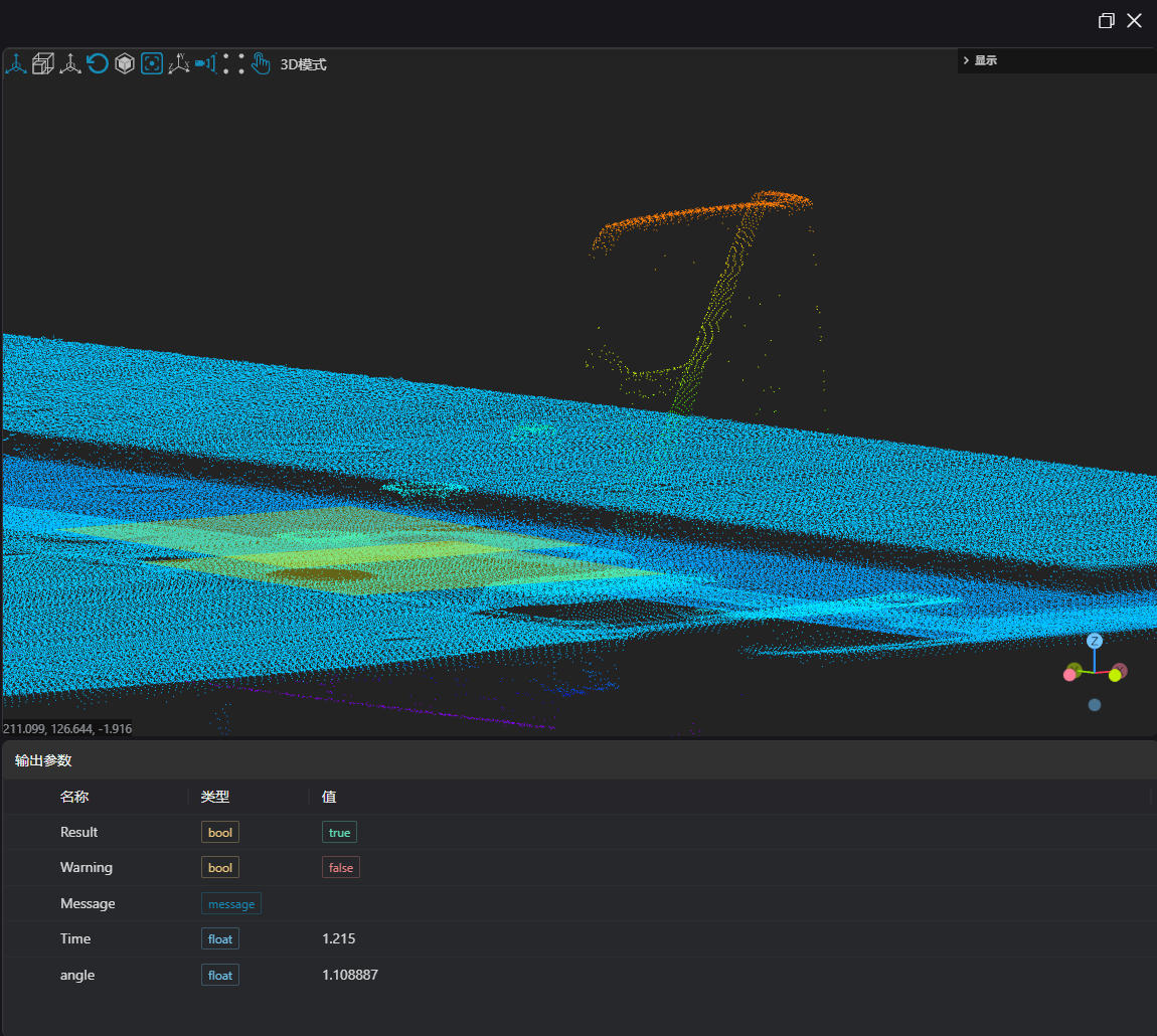
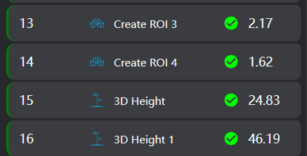
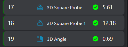
Project Results Display
- Inspection Results
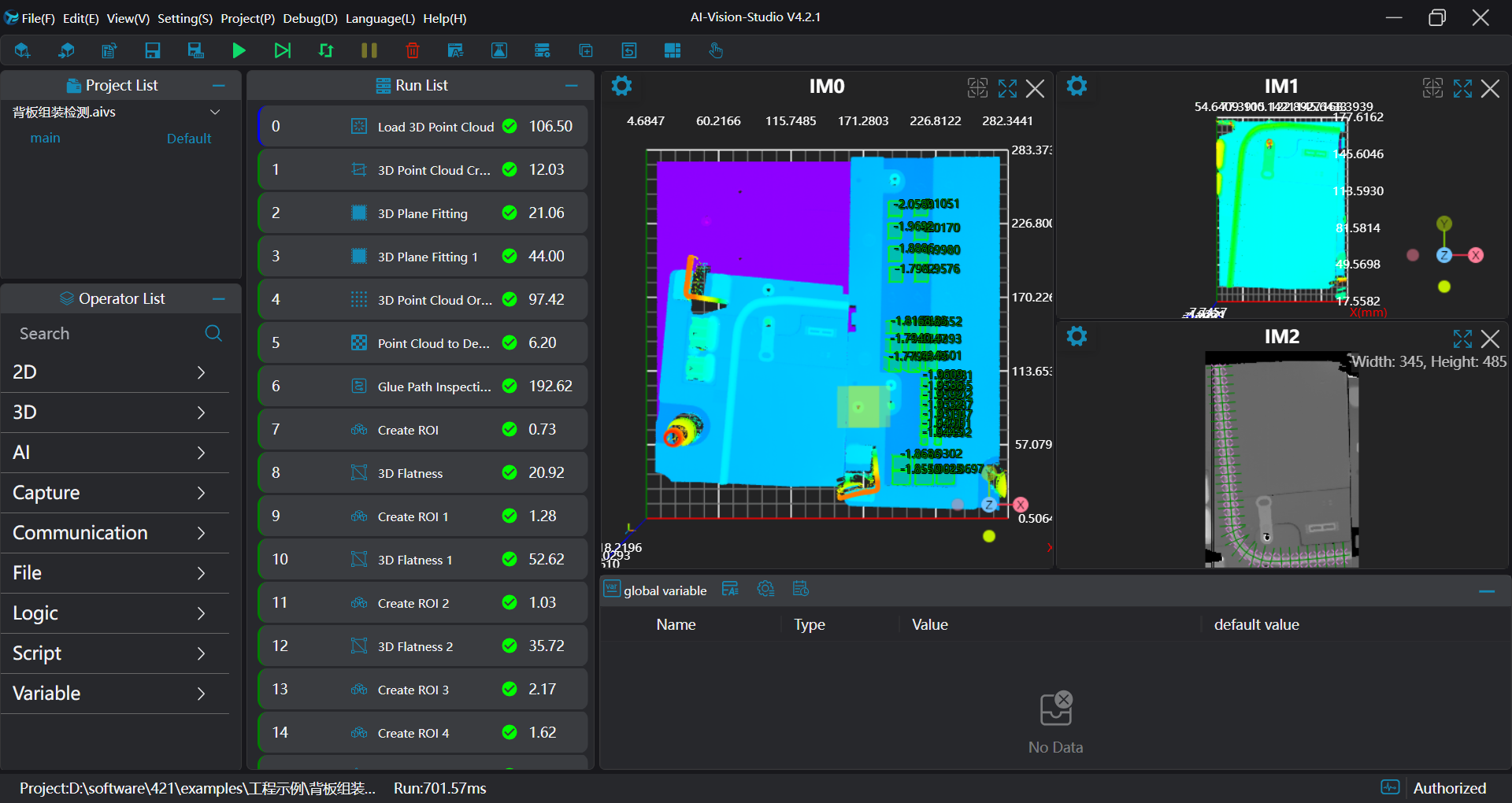
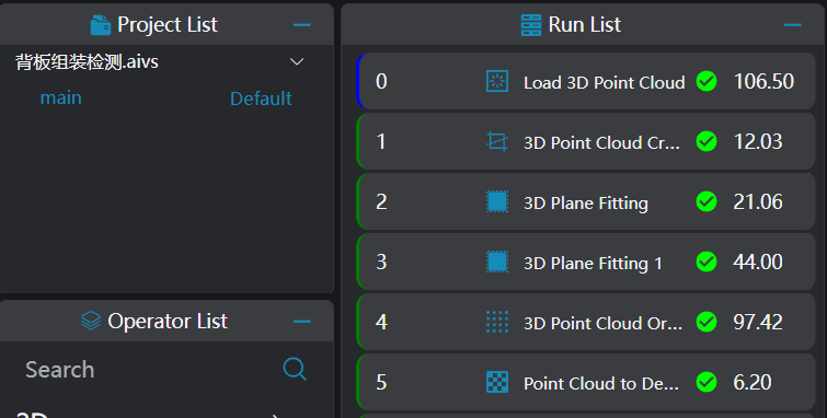
Project Process
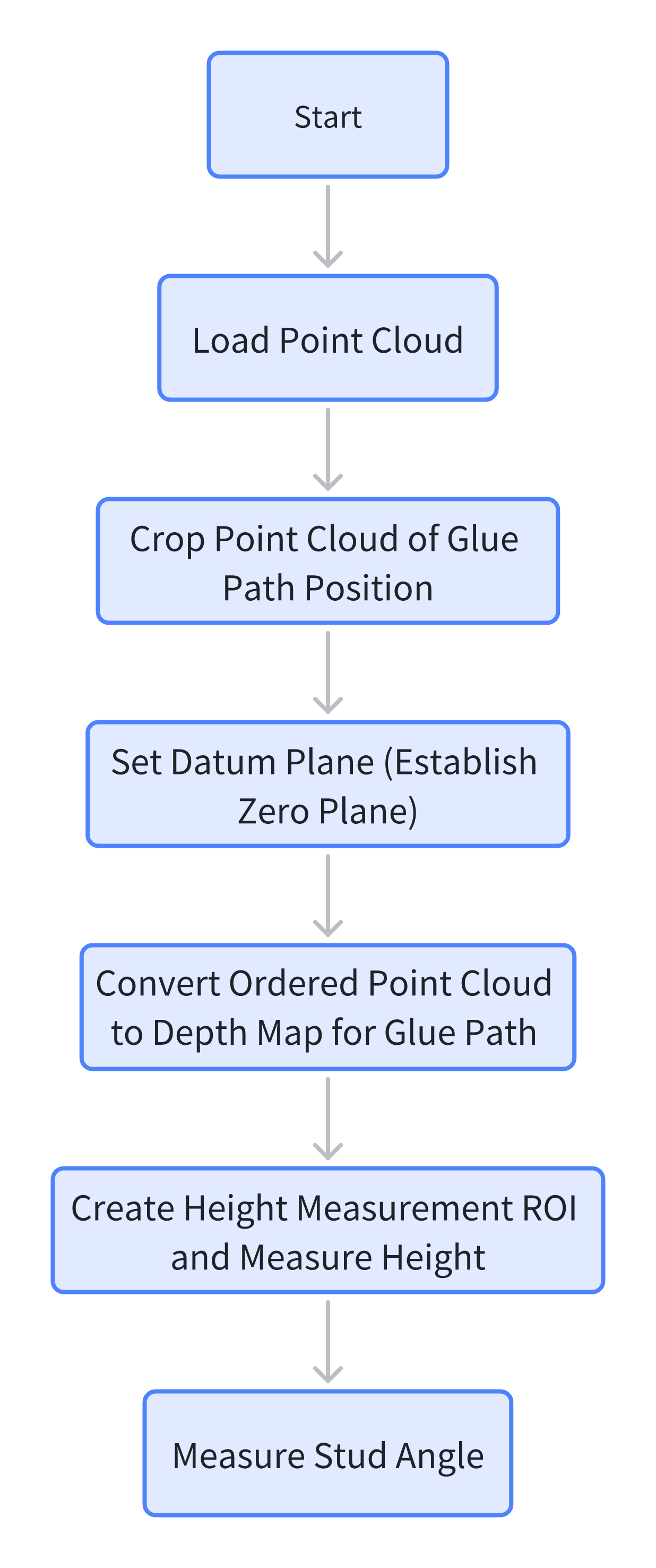
1. Initialization
Use the
Load Point Cloudtool to load the point cloud image that needs processing.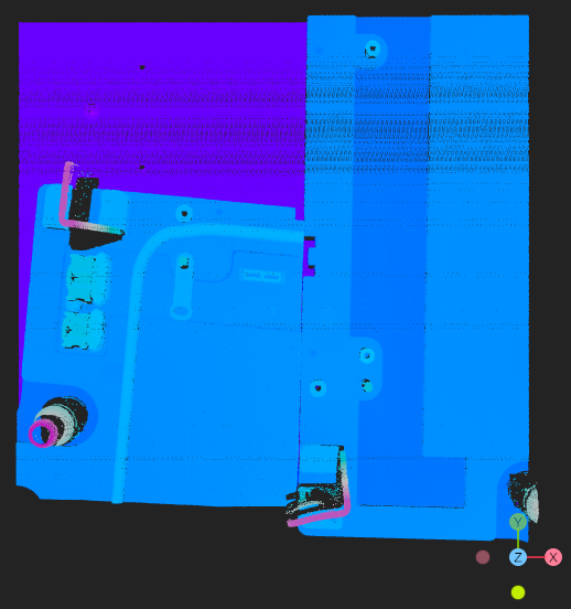
Use the
3D Point Cloud Croptool to crop the point cloud of the sealant path section.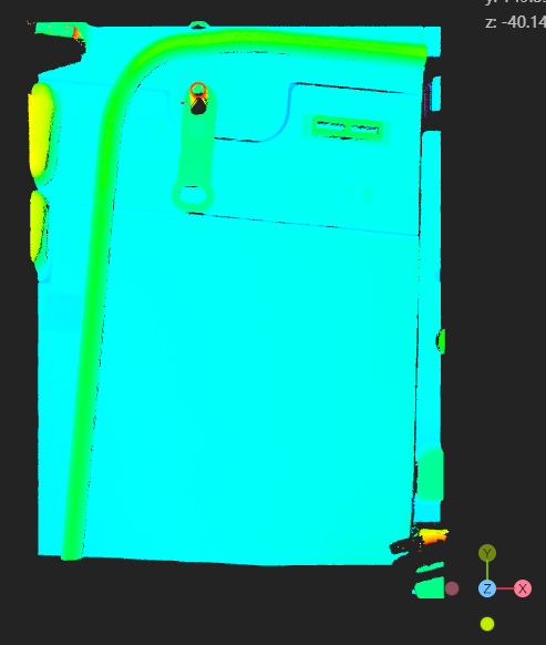
Use the
Plane Fittingtool to fit the plane for the sealant path point cloud and the datum plane of the initial point cloud, respectively.Use the
3D Point Cloud Orderingtool to set the XY direction resolution for the sealant path point cloud.Use the
Point Cloud to Depth Maptool, set the XY direction resolution, and convert the sealant path point cloud into a depth map.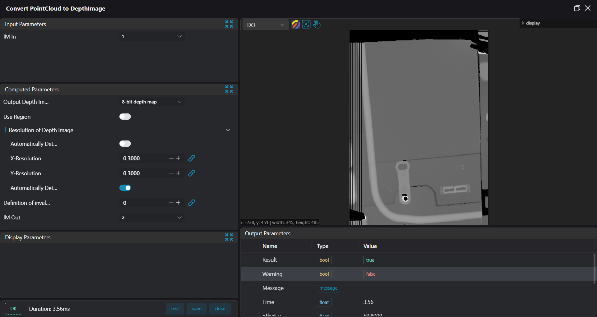
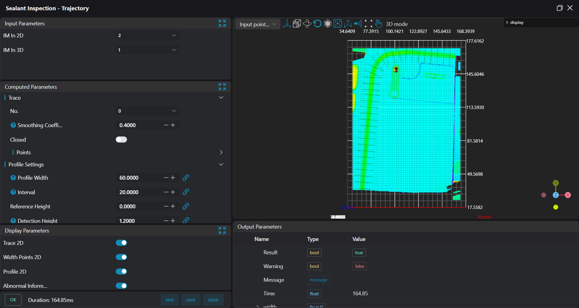
2. Sealant Path Inspection
Use the Sealant Path Inspection - Trajectory tool, input the point cloud and depth map, to detect the sealant path width and check for breaks. 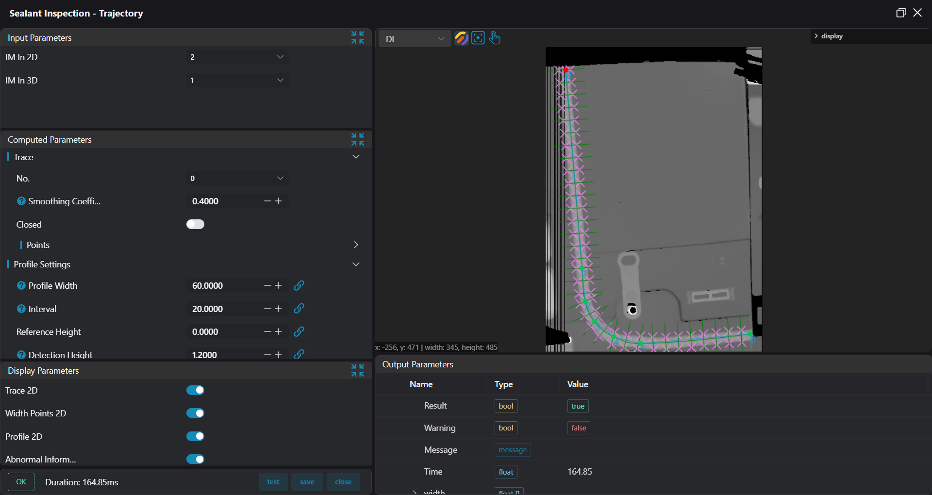
3. Flatness Inspection
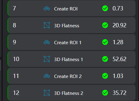
Use the
Create ROItool to create a box array.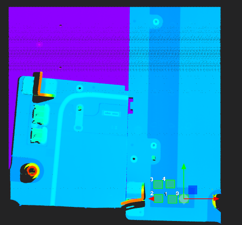
Use the
3D Flatnesstool, bound to the ROI array created in the previous step, to measure the regional flatness.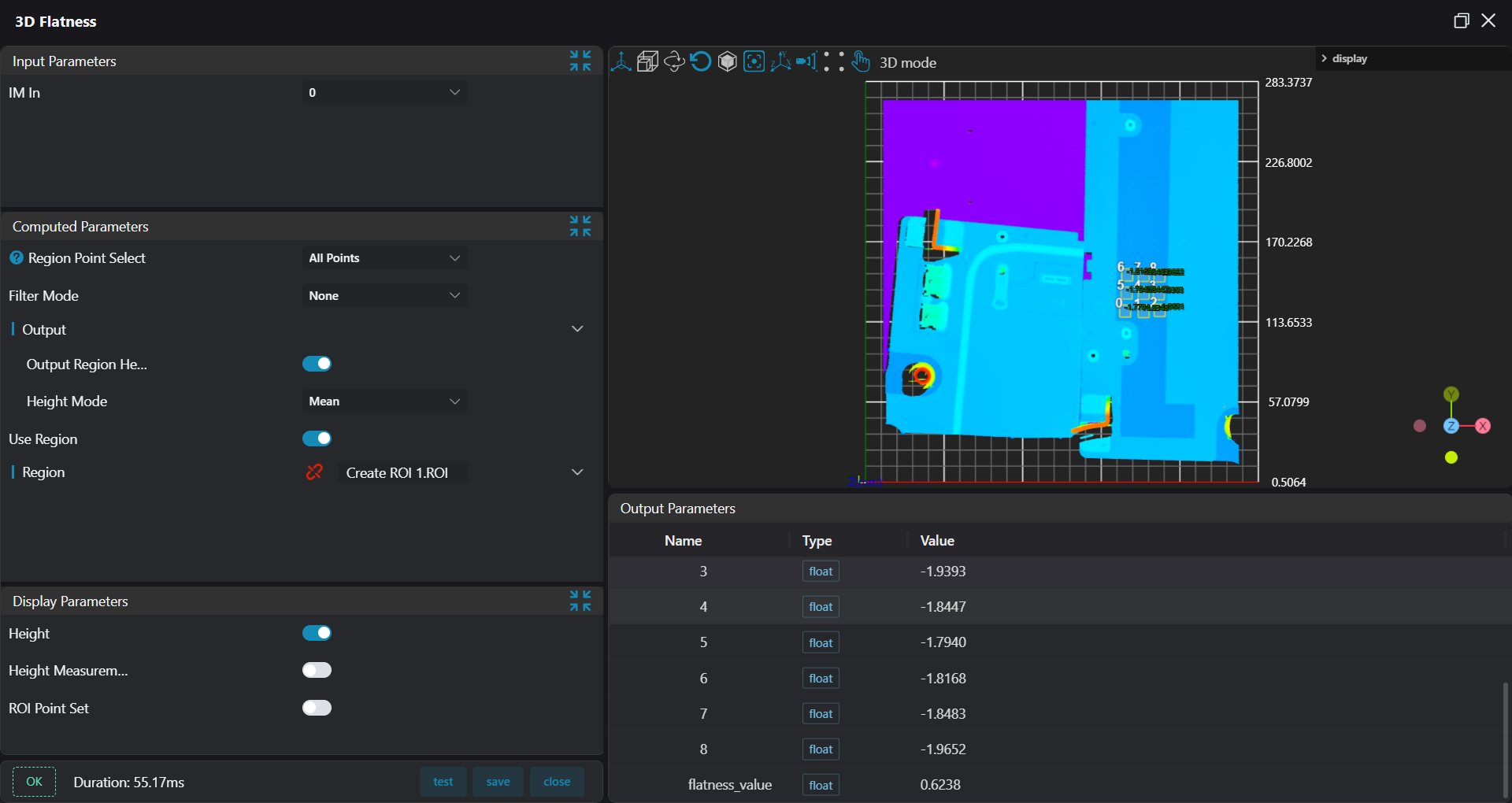
4. Height Measurement
Use the
Create ROItool to create box arrays on the PCB board and the reference area, respectively.
Use the
3D Flatnesstool, bound to the ROI arrays created in the previous step, to measure the height of the PCB board and the reference area respectively.
5. Stud Angle Measurement
Use the
3D Square Probetool to find the planes of the stud surface and the reference area, respectively.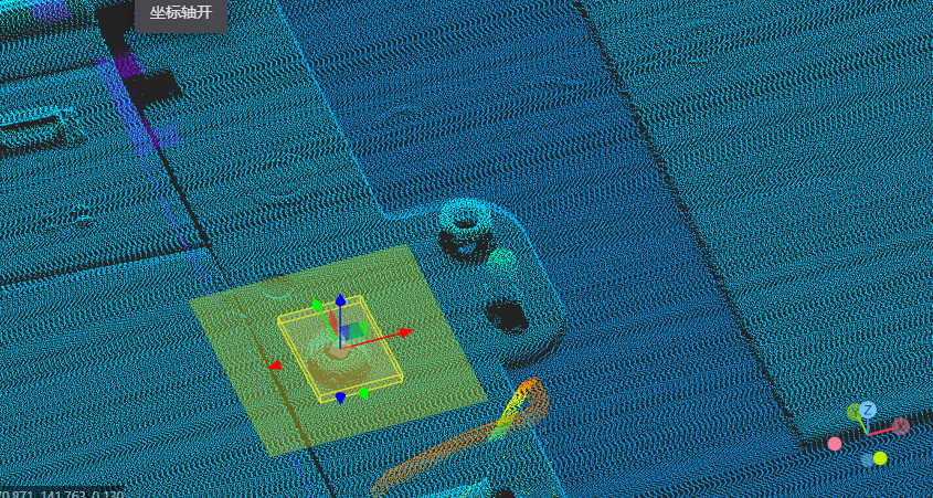
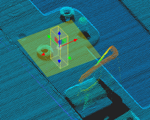
Use the
3D Angletool to calculate the angle between the stud surface and the reference area surface.