3D Geometric Intersection
Operator Function
Input object parameters to determine whether two objects intersect within the set tolerance range. If they intersect, output the intersection point (line) parameters.
Parameter Introduction
Input Parameters

| Parameter | Range | Default Value | Description | Illustration |
|---|---|---|---|---|
| Input Image | 0-8 | 0 | IM number for image input | |
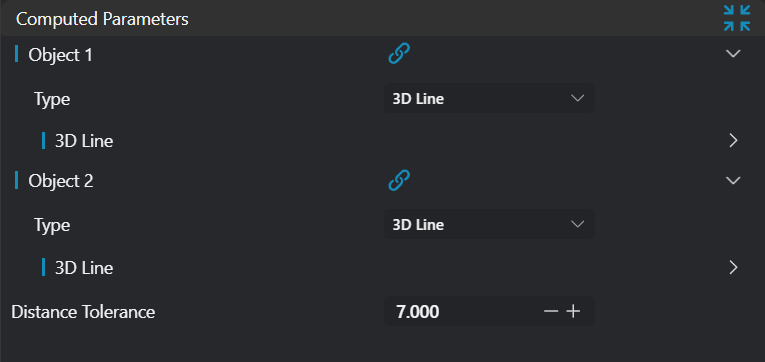
Calculation Parameters
| Parameter | Range | Default Value | Description | Illustration |
|---|---|---|---|---|
| Geometry 1 | 3D Line/Plane | 3D Line | See Geometry 1 | |
| Geometry 2 | 3D Line/Plane | 3D Line | See Geometry 2 | |
| Distance Tolerance | Only enabled when obtaining intersection of two lines. Set the distance tolerance between two lines. If beyond the set range, the lines are determined not to intersect | 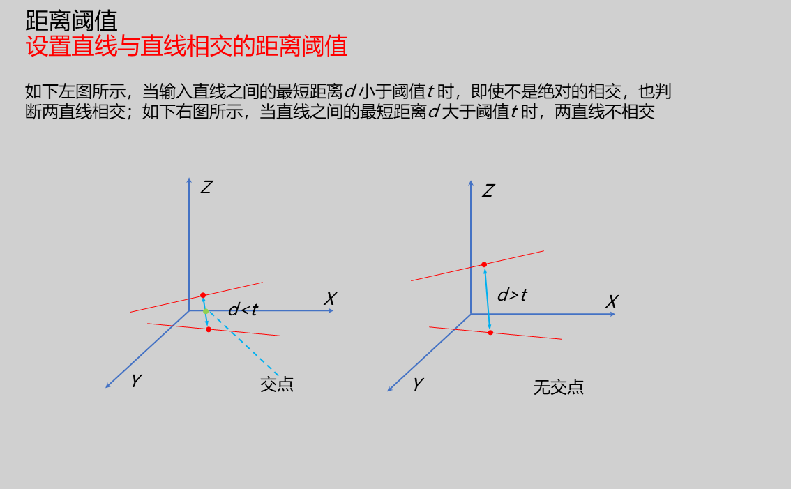 |
Geometry 1
| Parameter | Range | Default Value | Description | Illustration |
|---|---|---|---|---|
| Type | 3D Line/Plane | Set input type: 3D Line/Plane | ||
| Position | Enabled when input type is 3D Line/Plane. Input X, Y, Z coordinates of a point on the 3D line/plane | |||
| Direction | Enabled when input type is 3D Line. Input the direction vector of the line | |||
| Normal Vector | Enabled when input type is Plane. Input the normal vector of the plane |
Geometry 2
| Parameter | Range | Default Value | Description | Illustration |
|---|---|---|---|---|
| Type | 3D Line/Plane | Set input type: 3D Line/Plane | ||
| Position | Enabled when input type is 3D Line/Plane. Input X, Y, Z coordinates of a point on the 3D line/plane | |||
| Direction | Enabled when input type is 3D Line. Input the direction vector of the line | |||
| Normal Vector | Enabled when input type is Plane. Input the normal vector of the plane |
As shown below, when the second parameter is selected as a plane, it will determine whether the line and plane intersect. If they intersect, the intersection coordinates will be directly output:

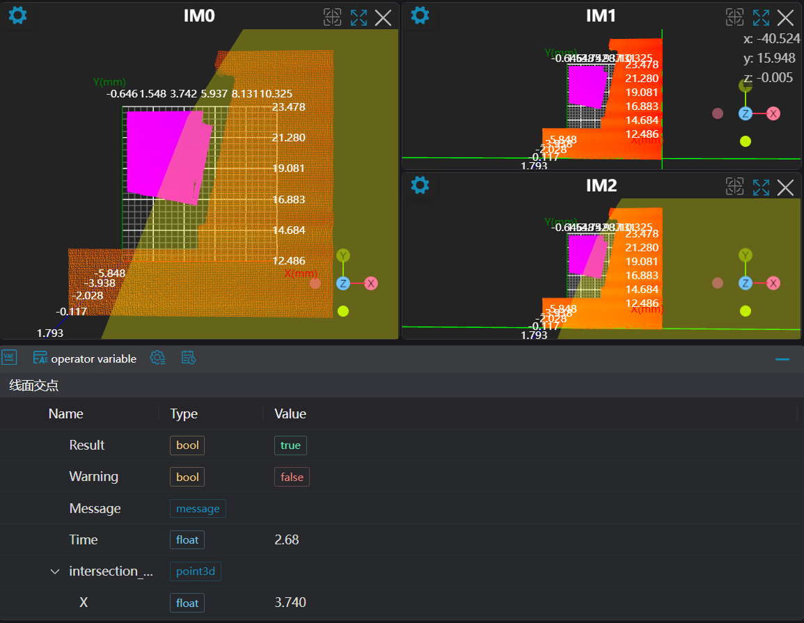
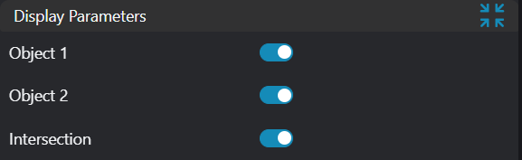
Result Display
| Parameter | Range | Default Value | Description | Illustration |
|---|---|---|---|---|
| Geometry 1 | true/false | false | If enabled, display Geometry 1 in the image | |
| Geometry 2 | true/false | false | If enabled, display Geometry 2 in the image | |
| Intersection Point | true/false | false | If enabled, display the intersection point in the image |
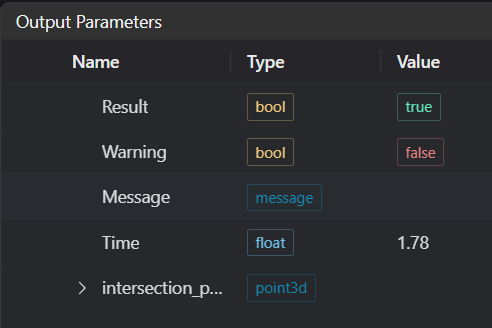
Output Parameters
| Name | Type | Range | Description |
|---|---|---|---|
| Result | bool | true/false | true for success false for failure |
| Warning | bool | true/false | true indicates a warning false indicates no warning |
| Message | string | Output success, error, or warning messages. Empty if no error or warning. | |
| Time | float | Operator execution time, unit: ms | |
| intersection_point | point3d | Output intersection point |
Tip
For more detailed explanations of parameter types, please refer to Type Definitions
Exception Troubleshooting
| No. | Exception Information | Corresponding Parameter | Solution |
|---|---|---|---|
| 1 | Input Geometry 1 type is {0}, invalid geometry type | Geometry Type | Input geometry type must be 3D Line/Plane |
| 2 | Input Geometry 1 line parameters are invalid | Input line direction vector parameters cannot be all zeros | |
| 3 | Input Geometry 2 line parameters are invalid | Input line direction vector parameters cannot be all zeros | |
| 4 | Input Geometry 2 plane parameters are invalid | Input plane normal vector parameters cannot be all zeros | |
| 5 | Input Geometry 2 type is {0}, invalid geometry type | Geometry Type | Second object type must be set to line or plane |
| 6 | Two lines do not intersect | Increase distance threshold |
Example Introduction
Engineering Design
Select the
Load Point Cloudtool to load the required 3D point cloud image to IM0.Select the
3D Croptool to copy IM0 to IM1 and IM2 respectively for different operations.Select multiple
3D Square Probetools to obtain two lines for line-line intersection, and one line and one plane for line-plane intersection.Select the
3D Geometric Intersectiontool.
Tool Usage
Select the input image for the operation. The image number must match the IM number where the image is located in the project.
Set inputs
Set different modes (line-line intersection, line-plane intersection), bind the lines or planes obtained from the previous step's square probe tools as inputs.
Set the parameters.
Check the content you want to display in the result display section.
Click
Testto check if the image window and parameters meet expectations.If there are no issues, click
Save. Run the operator in the run list, and then view the running results in the corresponding IM.