Aluminum Shell Surface Flatness Detection
Project Introduction
Project Background
With the continuous development of modern manufacturing industry, the requirements for product quality are becoming increasingly higher. As an important component of many products, the surface flatness of aluminum shells directly affects the overall performance and appearance quality of the products. Therefore, accurate measurement and control of aluminum shell surface flatness is particularly important.
Camera Selection
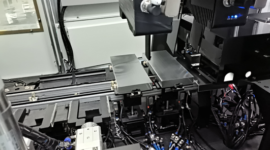
LMI Laser Line Scan Camera Gocator2430
Detection Requirements
Measurement accuracy ≤ 0.05mm
Measurement repeatability ≤ 0.018mm
Measurement cycle ≤ 200ms
Solution
AI-Vision software processes 3D point cloud images directly, performs localization, and conducts plane fitting on specified areas according to drawings for flatness measurement.
Design Concept
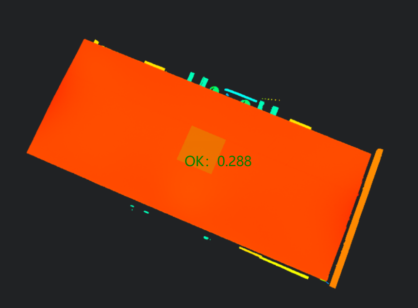
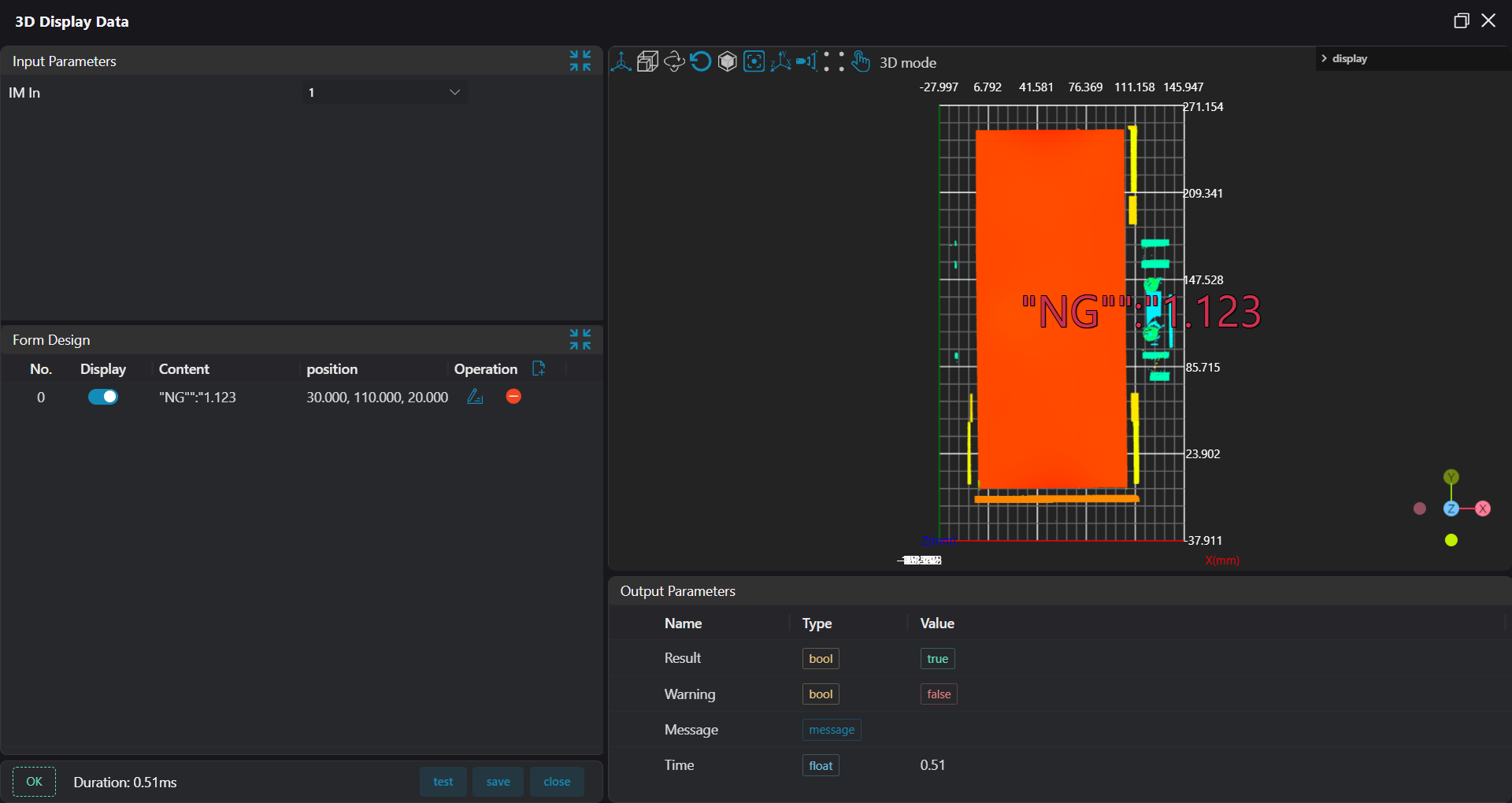
Execution Result Display
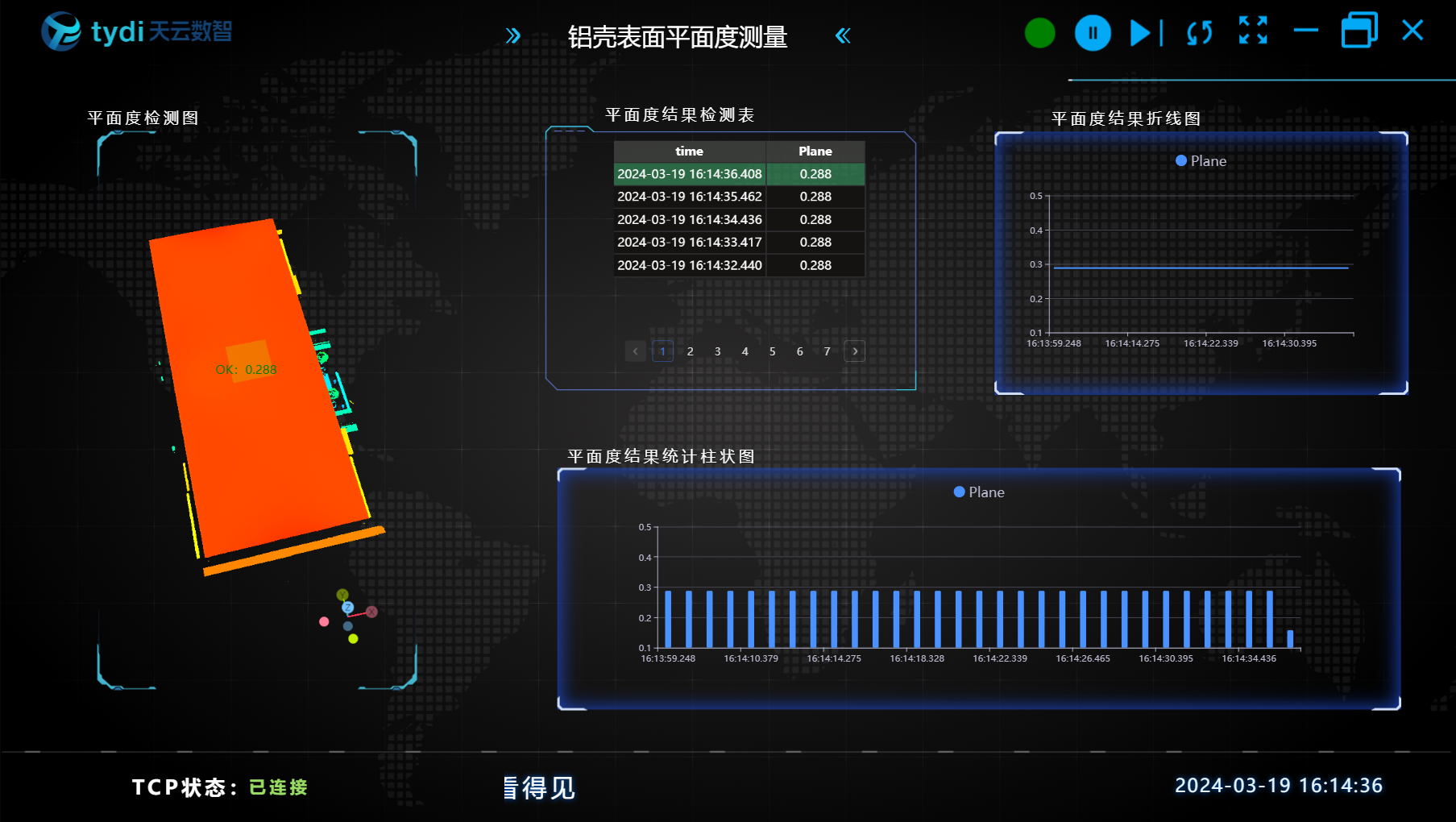
Project result display:
HMI result display:
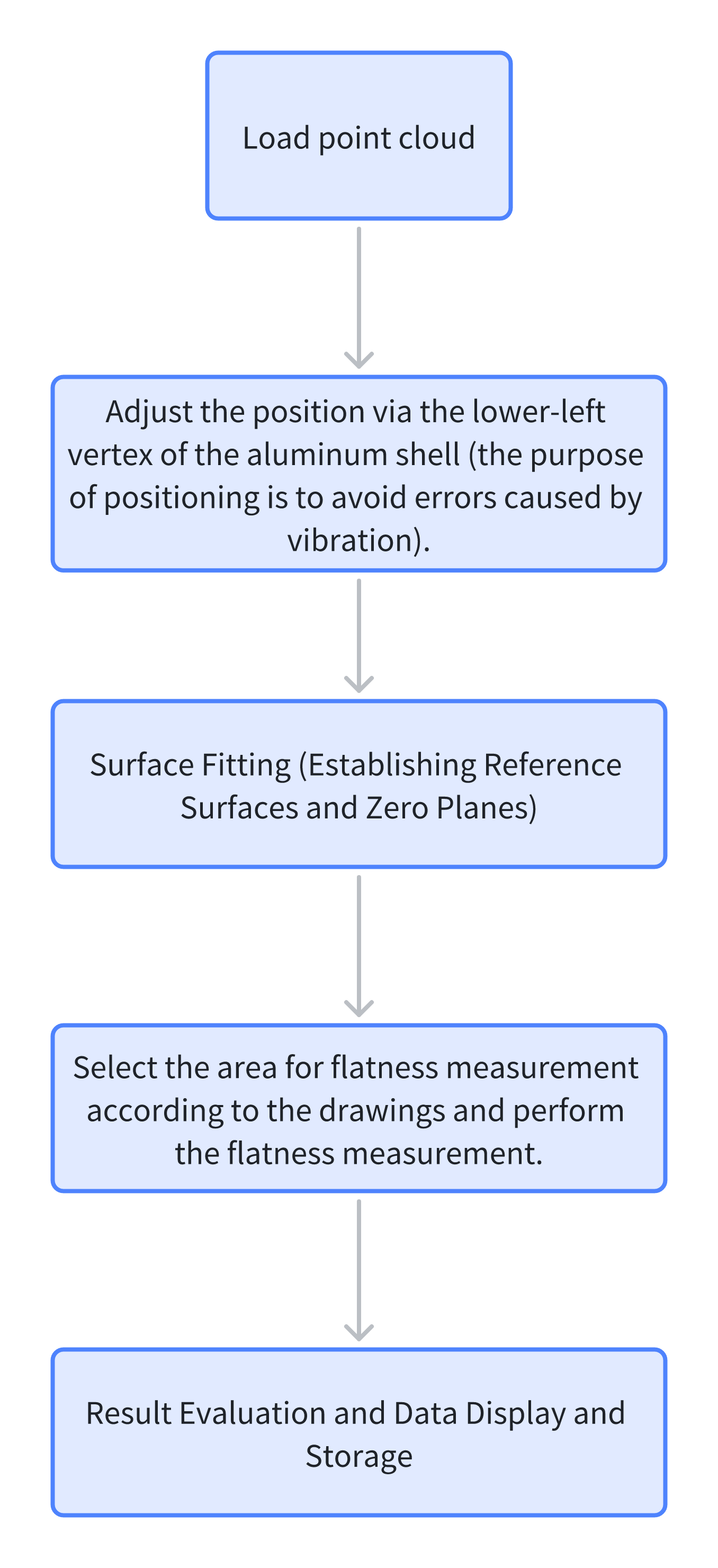
Project Process
One, Initialization
- Select
Load Point Cloudtool to obtain point cloud.
Two, Preprocessing
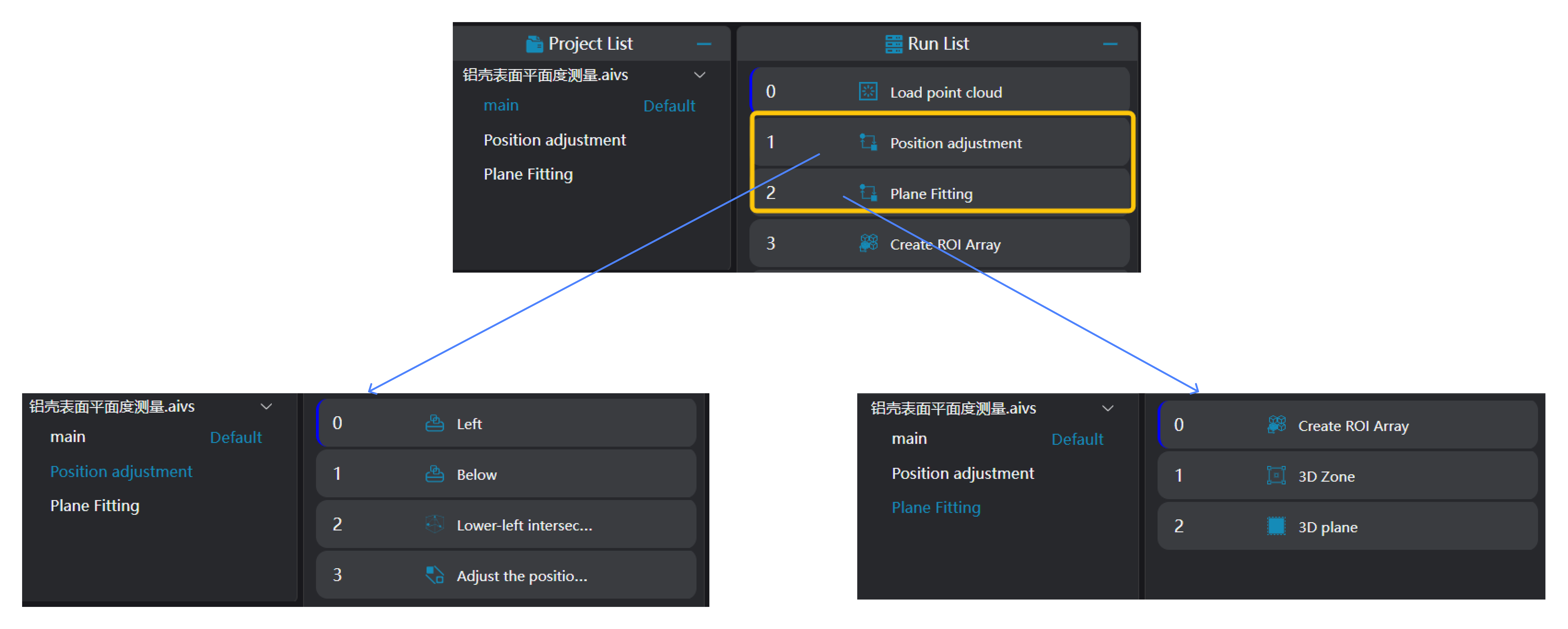
Position Adjustment
Select
3D Square Probetool twice to find the left and bottom straight lines of the aluminum shell.Select
3D Geometry Intersectiontool, bind the two edges output from the previous step as input geometry to find the intersection point of the two edges.
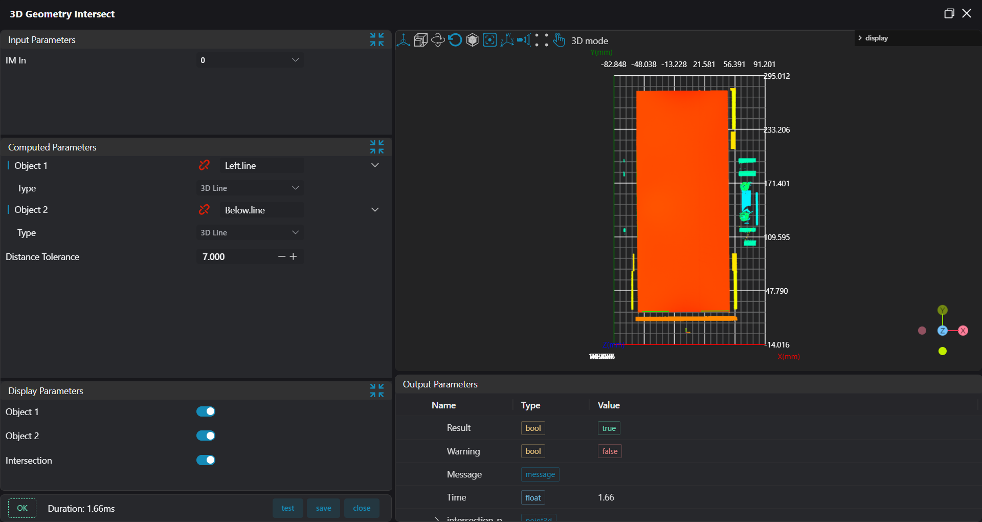
- Select
3D Position Adjustmenttool, bind the intersection point found by3D Geometry Intersectiontool as origin, adjust x,y positions.
Plane Fitting:
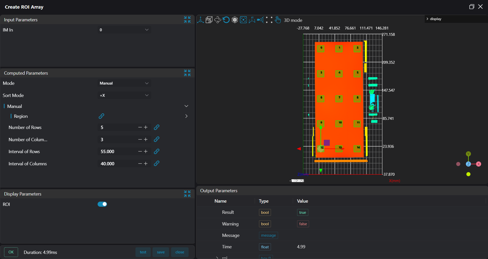
- Select
Create ROI Arraytool, select 15 different ROIs on the aluminum shell according to drawings.
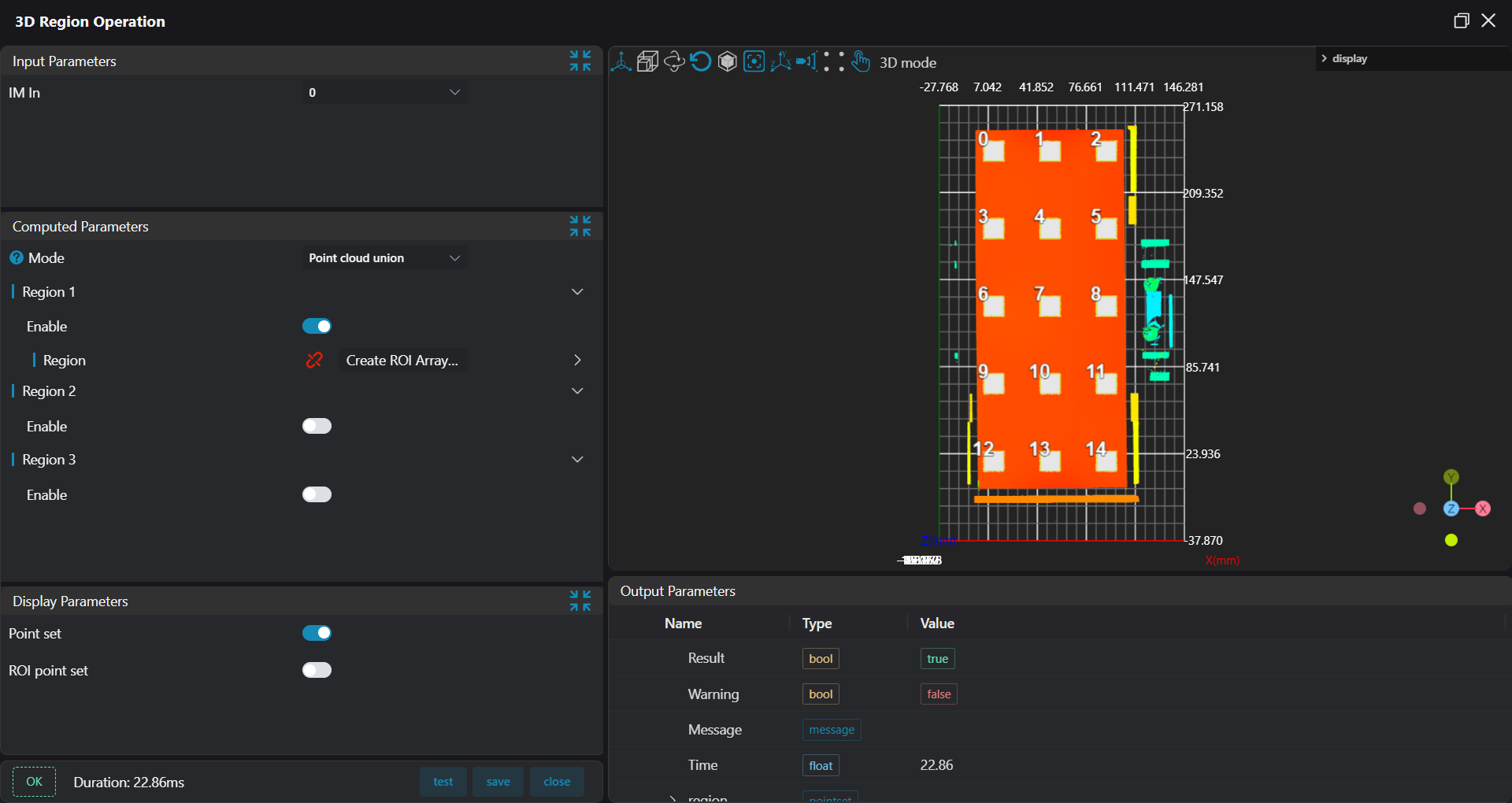
- Select
3D Regiontool, bind ROIs output fromCreate ROI Arraytool, integrate 15 ROI areas into one area.
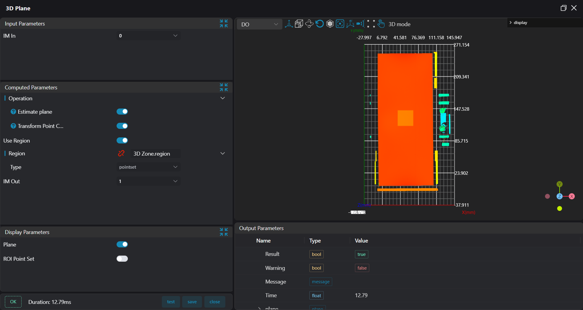
- Select
3D Planetool, bind the area set by the previous3D Regiontool as input area for plane fitting, and use the fitted plane as the 0 plane.
Three, Flatness Measurement
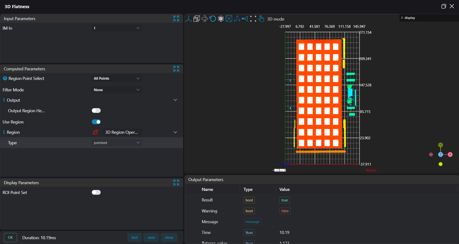
Select
Create ROI Arraytool, select 50 different ROIs on the aluminum shell according to drawings.Select
3D Flatnesstool, bind ROIs output from Create ROI Array, perform flatness measurement through the average points of the plane.
Four, Data Saving, Result Display and Judgment
Select
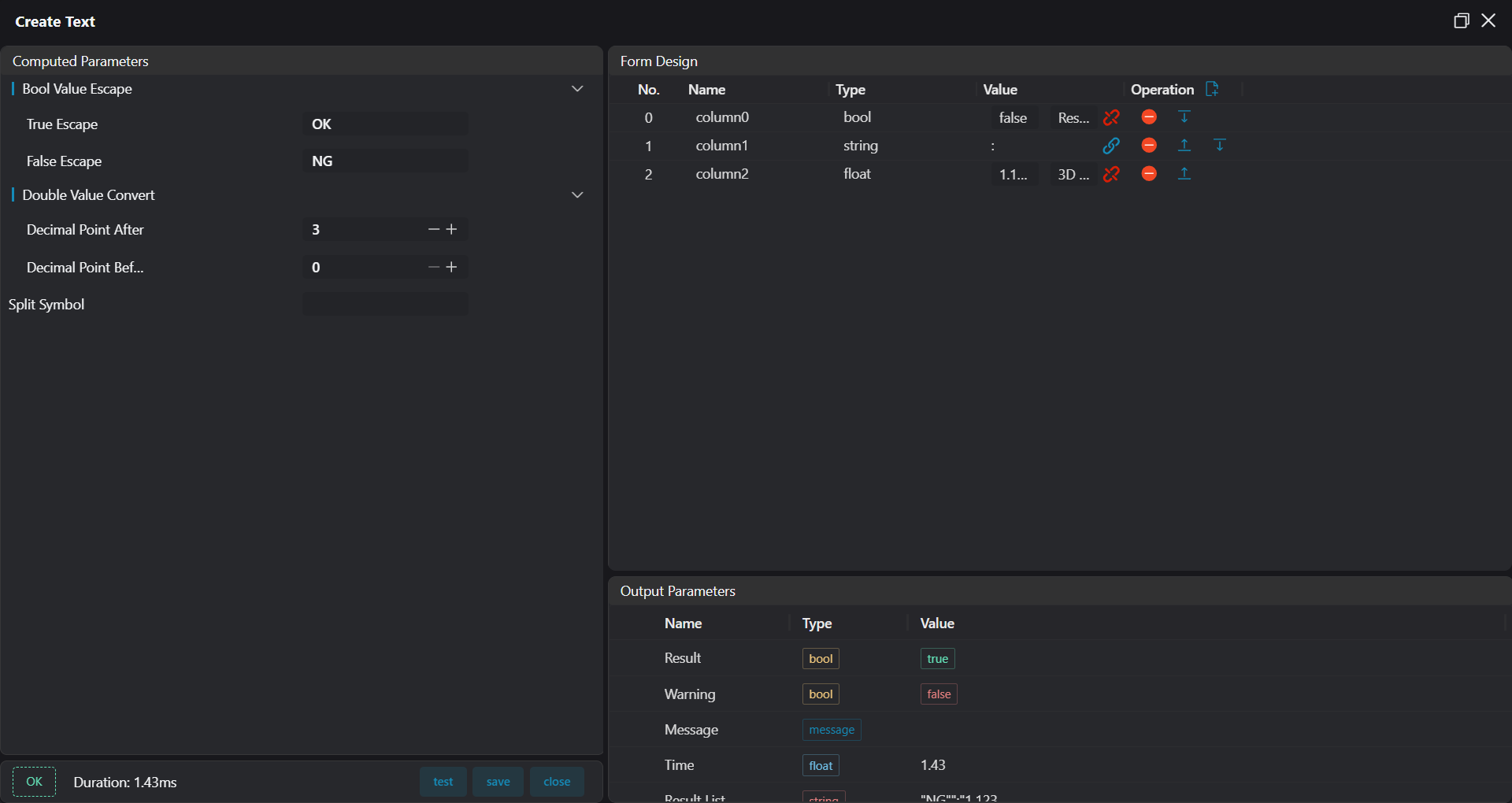
Data Checktool to judge flatness results.Select
Create Texttool to summarize displayed content into a string.
- Select
3D Result Displaytool, bind the string output fromCreate Texttool, display it at specified position in the image.
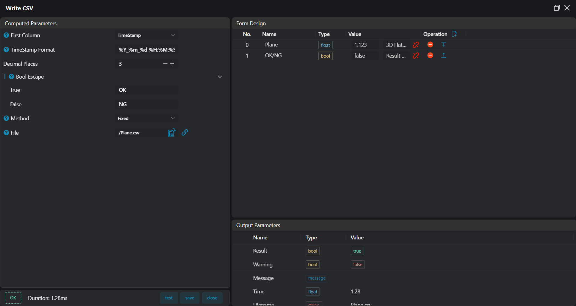
- Select
Write CSVtool, bind flatness results and OK/NG results, save results to corresponding csv file.