3D Point Cloud Edge
Operator Function
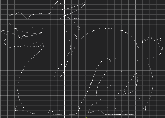
For the selected point cloud, output the 3D edge points of its XY plane projection.
Parameter Introduction
Input Parameters

| Parameter | Range | Default Value | Description | Illustration |
|---|---|---|---|---|
| Input Image | 0-8 | 0 | The IM number for image input |
Calculation Parameters
| Parameter | Range | Default Value | Description | Illustration |
|---|---|---|---|---|
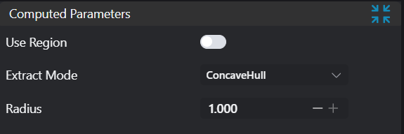
| Use Region Parameters | true/false | false | If enabled, use Region as input; if not enabled, use Input Image as input | |
| Region | 2D Window/2D Circular Window/2D Polygon Window/Box/Cylinder Box/Rotated Box/Point Set (binding only) | Box | Manually select an appropriate ROI regionCan bind to select existing ROI regions | |
| Extraction Mode | Latitude-Longitude Sweep/Concave Hull Algorithm/Normal Vector Extraction | Concave Hull Algorithm | Set extraction method. Latitude-Longitude Sweep is suitable for line scan camera images; Concave Hull Algorithm is suitable for projects with high accuracy requirements and relatively relaxed time constraints; Normal Vector Extraction is suitable for point clouds with significant curvature changes | |
| Resolution | 1-3000 | 5 | Resolution for Latitude-Longitude Sweep point cloud extraction; higher resolution extracts more edge points | 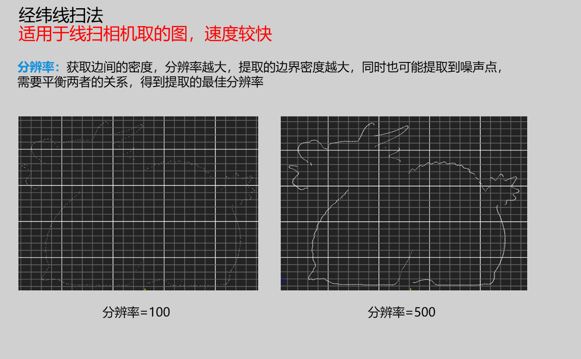 |
| Edge Point Density | 0.1-1.0 | 0.5 | Set edge point density for Concave Hull Algorithm; higher values extract more edge points but take more time | 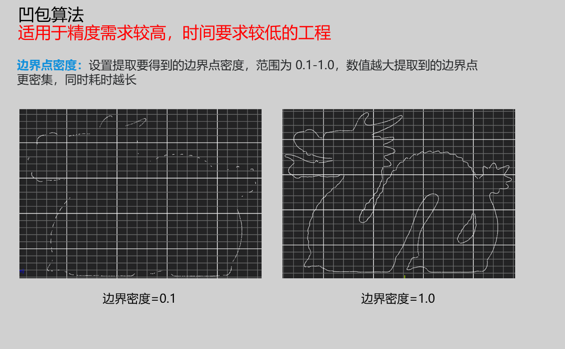 |
| K-Nearest Neighbors | 1-500 | 10 | Determines number of neighbors considered for boundary estimation; higher values ignore local details; adjust to balance noise and local details | 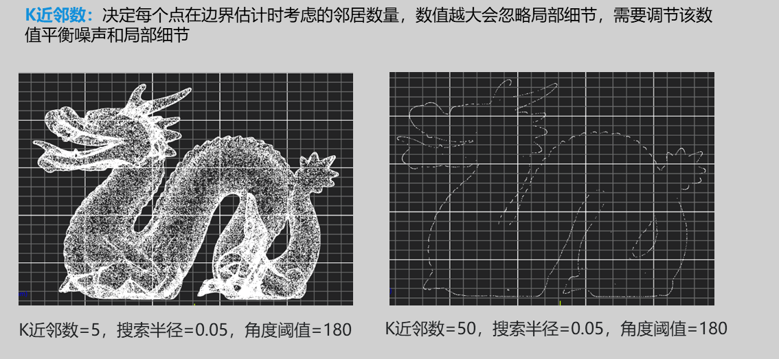 |
| Search Radius | 0.01-100.0 | 0.05 | Local range for normal vector calculation; affects normal vector estimation accuracy and noise resistance; increase for high-density point clouds to smooth noise; decrease for sparse point clouds to preserve details | 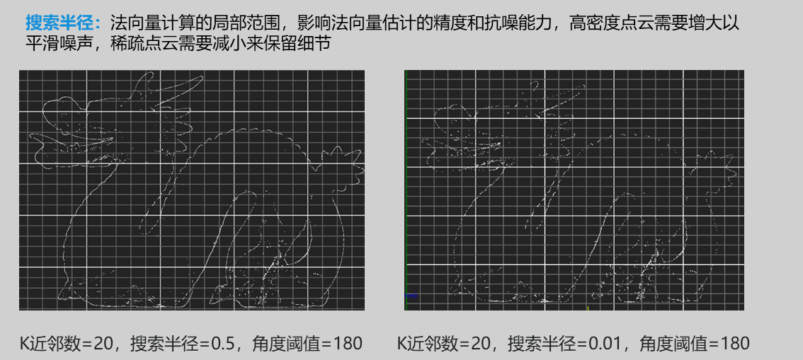 |
| Angle Threshold | 0-180 | 120 | Higher values needed for more complex point clouds; threshold for normal vector angle to determine boundary points; values exceeding this are considered boundaries; generally set to 180 when extracting projection plane boundaries | 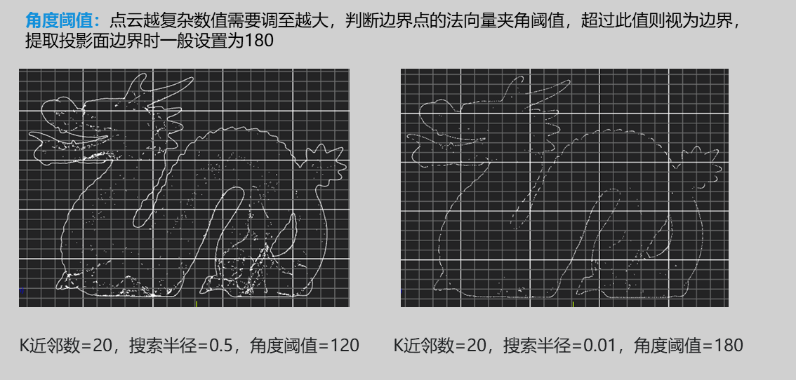 |
Result Display
| Parameter | Range | Default Value | Description | Illustration |
|---|---|---|---|---|
| Boundary | true/false | false | Extracted 3D edge points |
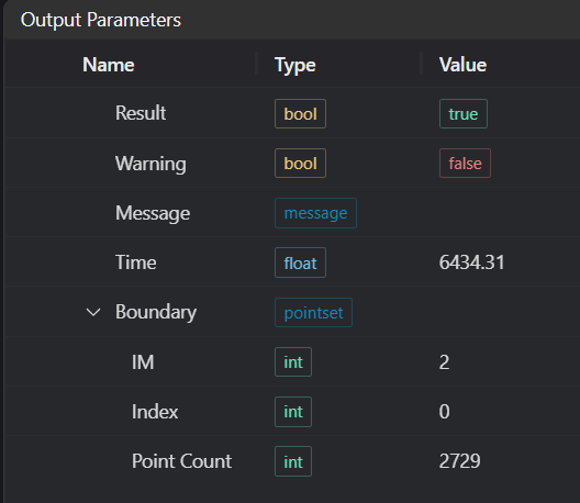
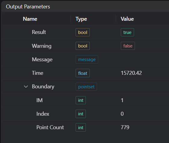
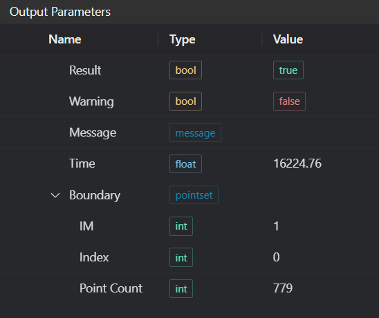
Output Parameters
| Name | Type | Range | Description |
|---|---|---|---|
| Result | bool | true/false | true for success false for failure |
| Warning | bool | true/false | true indicates there is a warning false indicates there is none |
| Message | string | Outputs success, error, or warning information; if there is no error or warning, it is empty | |
| Time | float | Operator execution time, unit: ms | |
| boundary | pointset | Edge point cloud |
Tip
For more detailed explanations of parameter types, please refer to Type Definitions
Exception Troubleshooting
| No. | Exception Information | Corresponding Parameter | Solution |
|---|---|---|---|
| 1 | Input region type is {0}, invalid region type | Region Type | Region input type must be one of: 2D Window/2D Circular Window/2D Polygon Window/Box/Cylinder Box/Rotated Box/Point Set |
| 2 | Region is empty | 1. Check if selection is empty 2. Check if point set is empty | |
| 3 | Input point cloud is empty | Confirm if IM contains valid points; if no valid points, load point cloud or switch to IM with valid points | |
| 4 | Output edge is empty | Adjust parameters of relevant mode | |
| 5 | Input extraction mode is {0}, invalid extraction mode | Extraction Mode | Set extraction mode to one of: Latitude-Longitude Sweep/Concave Hull Algorithm/Normal Vector Extraction |
| 6 | Input polygon vertex count less than 3, cannot form polygon | Add 2D polygon window vertices so vertex count is at least three |
Example Introduction
Engineering Design
Select the
Load Point Cloudtool to load the 3D point cloud image to be processed into IM0;Select the
3D Point Cloud Edgetool.
Tool Usage
Select the input image for operation; the image number must match the IM number where the image is located in the project.
Either do not enable Use Region Parameters, or enable region and select region type as Box, move the box to the position to be measured, enclosing the point cloud to be measured.
Usage Tips
1. Use the ROI controller on the image window to drag or scale the box;
2. Directly modify the start or end coordinates of the box in the calculation parameters to adjust the box position and size.
Set parameters
Check the content you want to display in the result display section
Click
Testto check if the image window and parameters meet expectationsIf there are no issues, click
Save, then run the operator in the run list to view the results in the corresponding IM
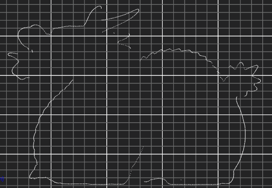
Latitude-Longitude Sweep Method
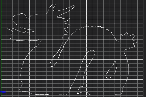
Concave Hull Method
Normal Vector Extraction Method