2D Line Intersection
Operator Function
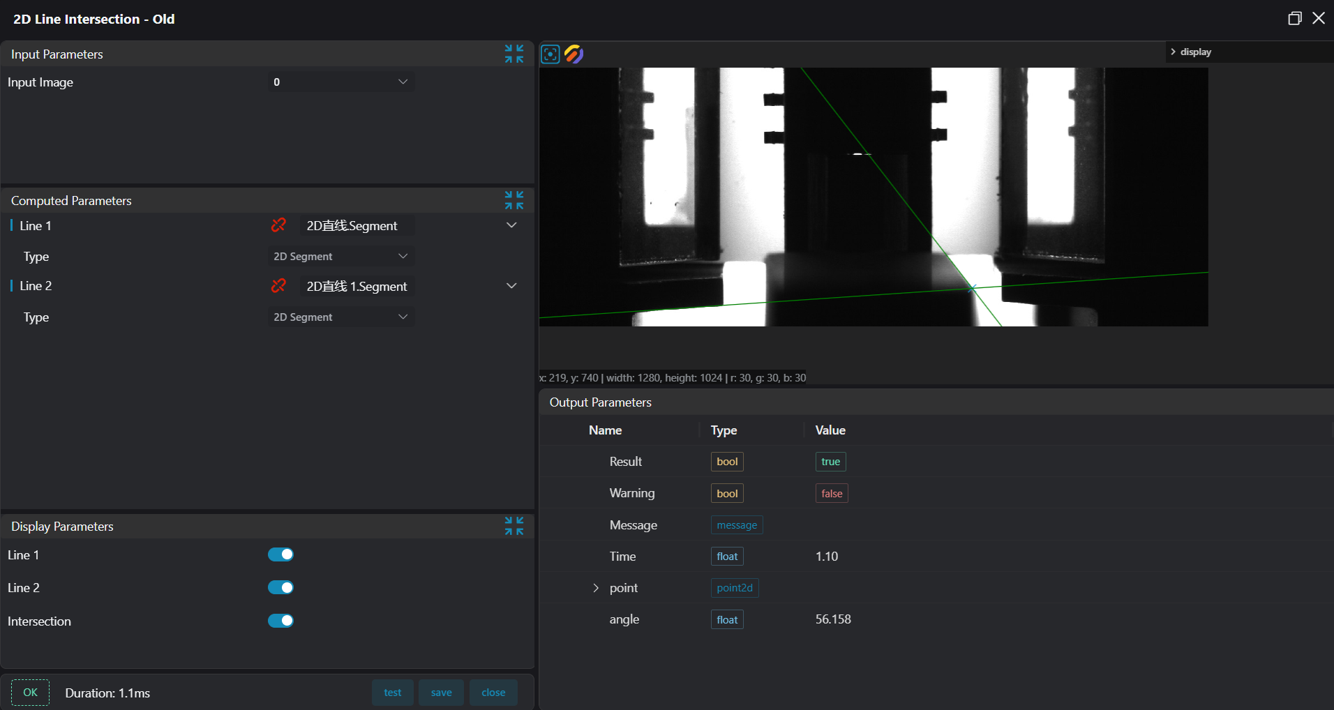
Input the parameters of lines/segments, determine whether two objects intersect within the set tolerance range, and if they do, output the intersection coordinates to the register.
Parameter Introduction
Input Parameters
| Parameter | Range | Default Value | Description | Illustration |
|---|---|---|---|---|
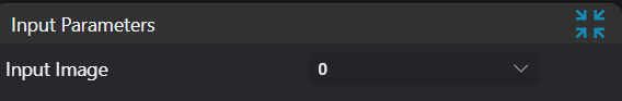
| Input Image | 0-8 | 0 | IM number for image input | |
Calculation Parameters
| Parameter | Range | Default Value | Description | Illustration |
|---|---|---|---|---|
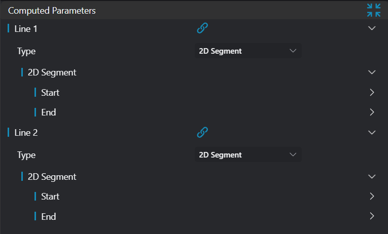
| Line 1 | 2D Line/2D Segment | 2D Segment | Manually set appropriate line or segmentCan bind to select existing R line or segment | |
| Line 2 | 2D Line/2D Segment | 2D Segment | Manually set appropriate line or segmentCan bind to select existing R line or segment |
Extend the line segments to find the intersection point, α is the angle between the lines, P(x,y) is the intersection point coordinates. 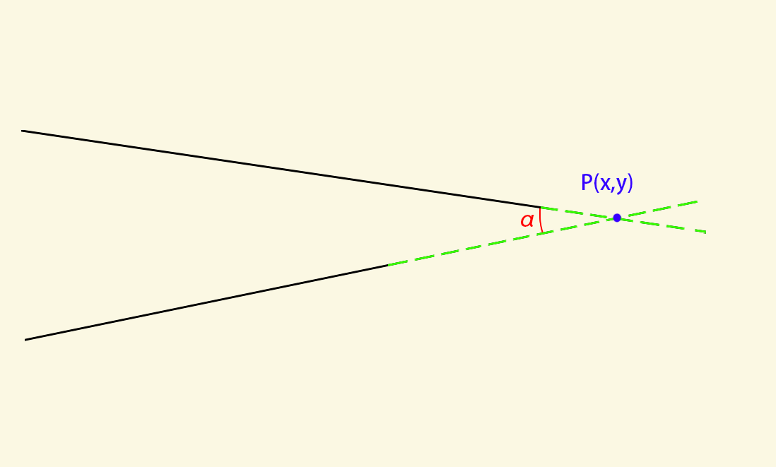
Result Display
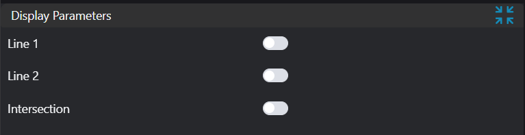
| Parameter | Range | Default Value | Description | Illustration |
|---|---|---|---|---|
| Line 1 | true/false | false | If enabled, display the first line on the image | |
| Line 2 | true/false | false | If enabled, display the second line on the image | |
| Intersection Point | true/false | false | If enabled, display the intersection point of the two lines on the image |
Output Parameters
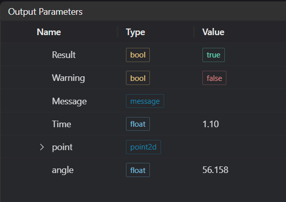
| Name | Type | Range | Description |
|---|---|---|---|
| Result | bool | true/false | true for success false for failure |
| Warning | bool | true/false | true indicates a warning false indicates no warning |
| Message | string | Output success, error, or warning messages. Empty if no error or warning. | |
| Time | float | Operator execution time, unit: ms | |
| point | point2d | Intersection point XY information of the two lines | |
| angle | float | Angle information at the intersection of the two lines |
Exception Troubleshooting
| No. | Exception Information | Corresponding Parameter | Solution |
|---|---|---|---|
| 1 | Parallel, no intersection point | The input lines are parallel and have no intersection point | |
| 2 | Input image is empty | Check if the input image is empty |
Example Introduction
Engineering Design
Select the
Load Imagetool to load the required 2D image to IM0.Select two
2D Linetools to obtain two lines respectively.Select the
2D Line Intersectiontool.
Tool Usage
Select input image IM0.
Bind the two lines output by the previous
2D Linetools as Line 1 and Line 2.Check the content you want to display in the result display section.
Click
Testto check if the image window and parameters meet expectations.If there are no issues, click
Save. Run the operator in the run list, and then view the running results in the corresponding IM.