3D Square Probe
Operator Function
Search for edge points in a specific direction, returning geometric parameters such as points, lines, planes, regions, etc.
Parameter Introduction
Input Parameters

| Parameter | Range | Default Value | Description | Illustration |
|---|---|---|---|---|
| Input Image | 0-8 | 0 | The IM number for image input | |
Calculation Parameters
| Parameter | Range | Default Value | Description | Illustration |
|---|---|---|---|---|
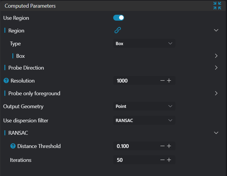
| Region | 2D Window/Box | Box | Manually select an appropriate ROI regionCan bind to select existing ROI regions | |
| Direction | +X/-X/+Y/-Y/+Z/ -Z/Select All Points | Select All Points | Select search direction +X: Search along positive X-axis -X: Search along negative X-axis +Y: Search along positive Y-axis -Y: Search along negative Y-axis +Z: Search along positive Z-axis -Z: Search along negative Z-axis Select All Points: Select all points within ROI | 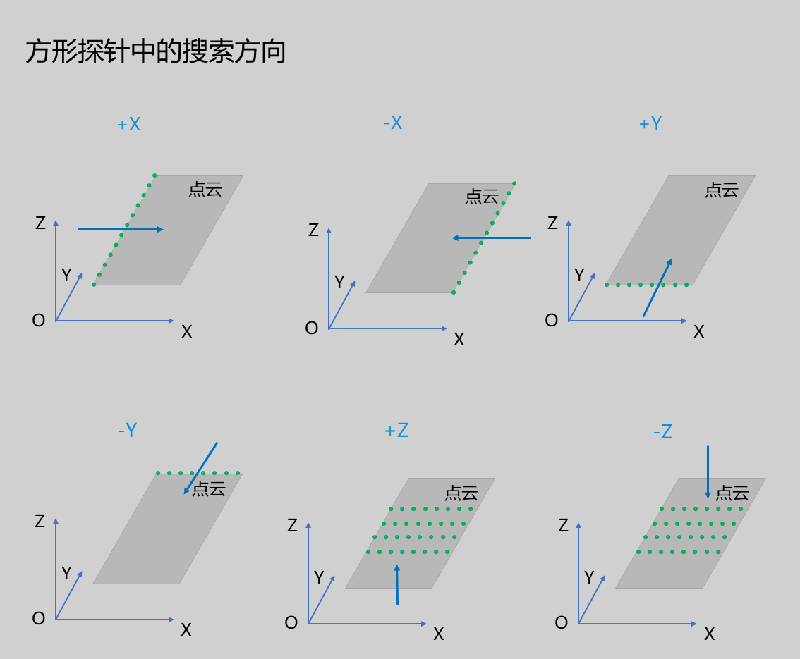 |
| Exclusion Cone Angle | 45.000 | The cone angle when searching along the selected direction; points outside the cone will be preserved | 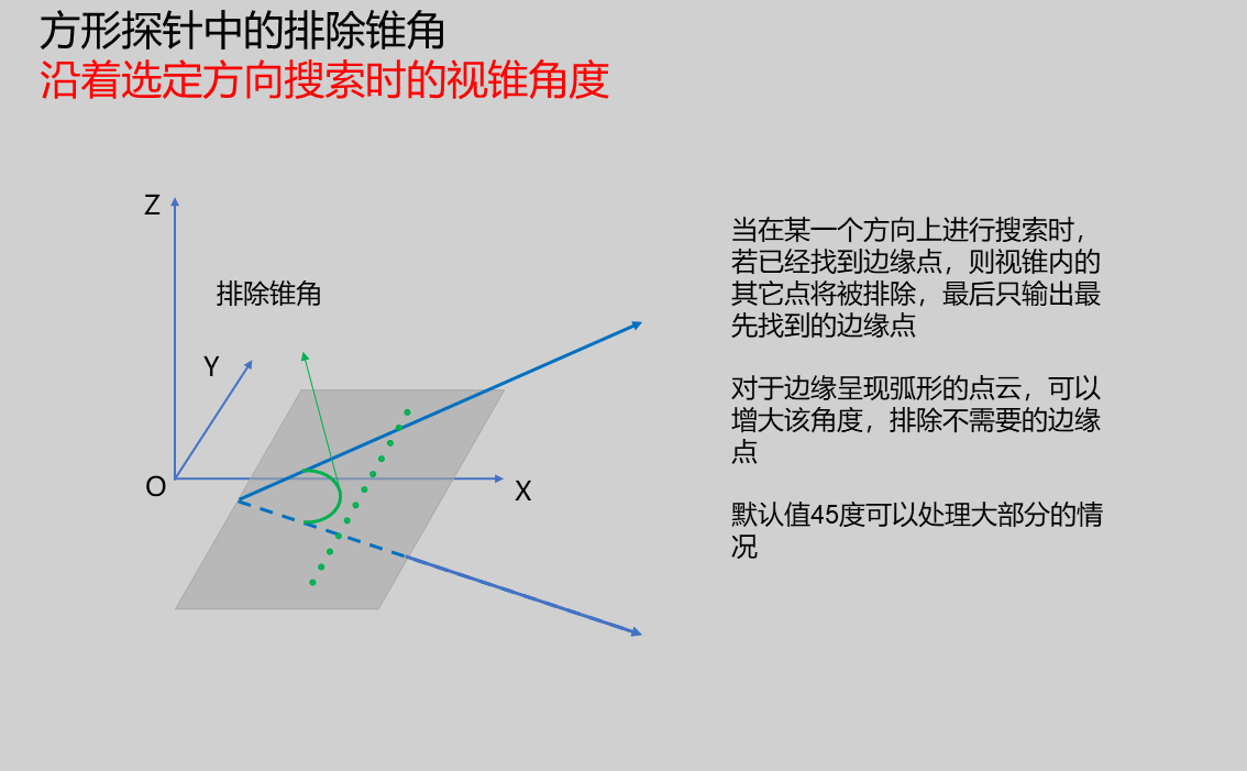 | |
| Resolution | 1000 | The reciprocal of step length when searching along the selected direction; increasing resolution means more sampling points, but also increases operator runtime. | 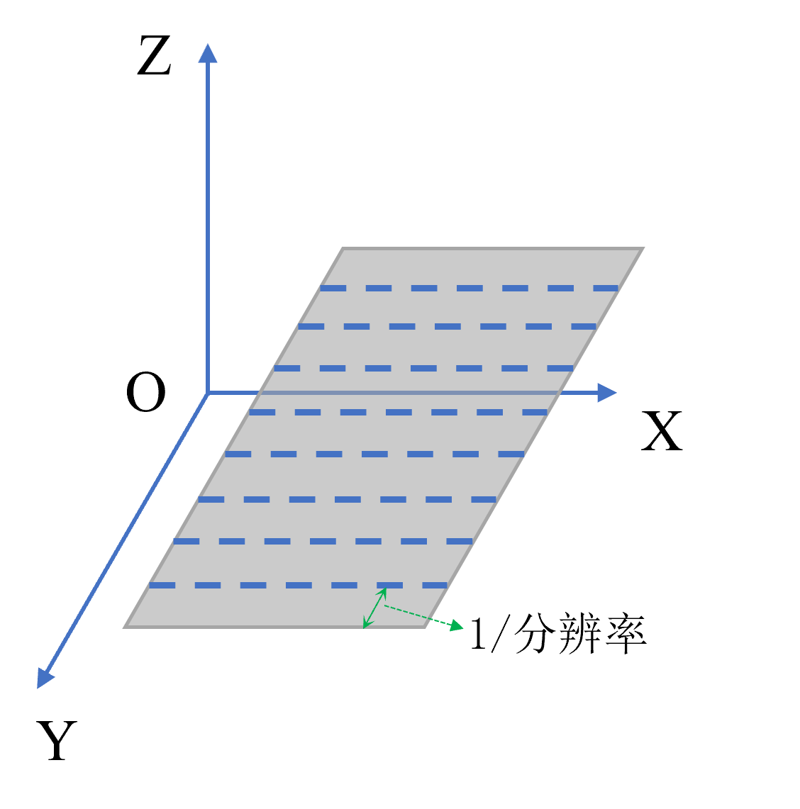 | |
| Search Foreground Only | Whether to only search for foreground edge points; if checked, manually set Z-direction threshold to separate foreground and background. | 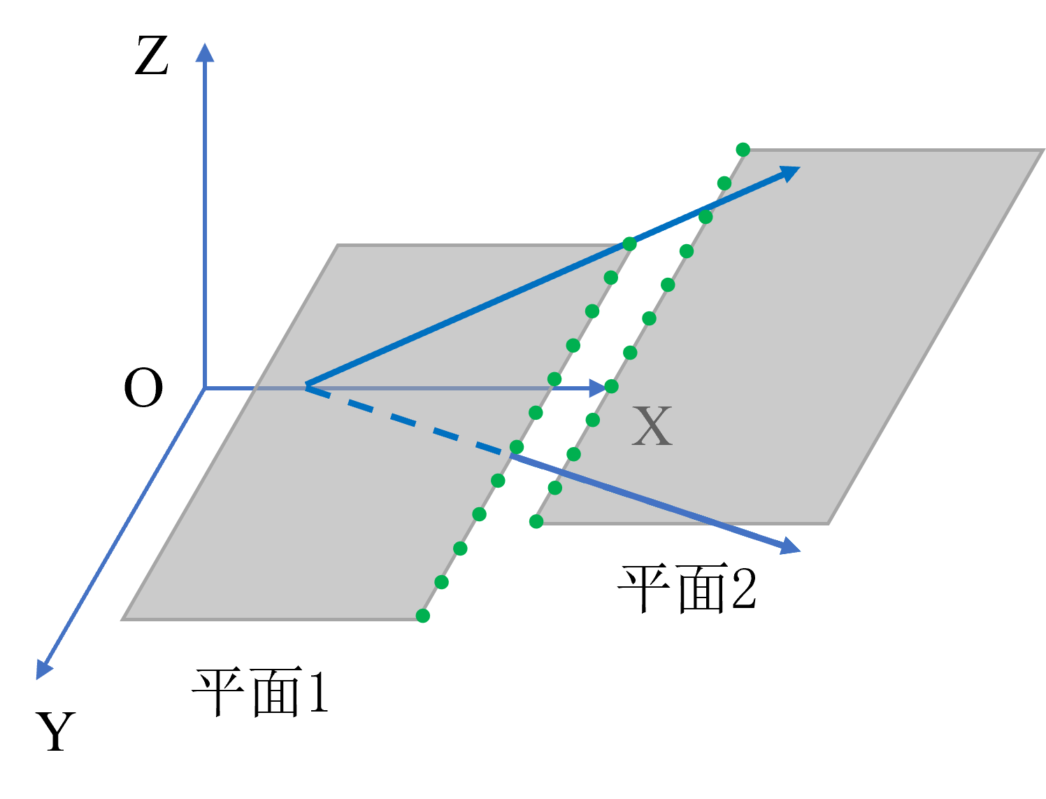 | ||
| Output Geometry | Point/Line/Plane/Segment | Line | Point: Centroid coordinate point of point cloud region Line: Contains center point of line segment and direction vector of line Plane: Contains geometric center point of plane and normal vector of plane Segment: Contains coordinates of two endpoints of line segment | |
| Filter Method | No Filter/Statistical Filter/RANSAC Filter | No Filter | See Filter Methods |
Result Display
| Parameter | Range | Default Value | Description | Illustration |
|---|---|---|---|---|
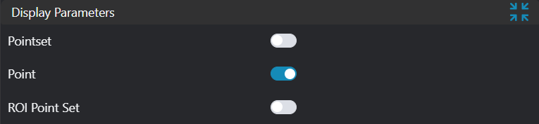
| Point Set | true/false | false | Target point set; if enabled, displayed in the image | |
| Point | true/false | false | Points found by the tool; if enabled, displayed in the image | |
| Line | true/false | false | Lines found by the tool; if enabled, displayed in the image | |
| Plane | true/false | false | Planes found by the tool; if enabled, displayed in the image | |
| ROI Point Set | true/false | false | Point set of ROI selected region; if enabled, displayed in the image | |
| Segment | true/false | false | Line segments found by the tool; if enabled, displayed in the image | |
| Segment Center Point | true/false | false | Midpoints of line segments found by the tool; if enabled, displayed in the image |
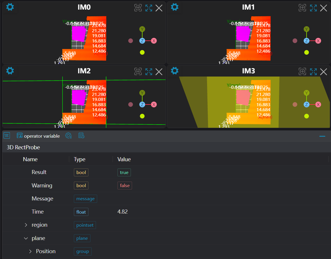
Output Parameters
| Name | Type | Range | Description |
|---|---|---|---|
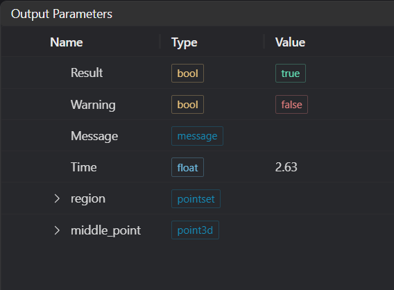
| Result | bool | true/false | true for success false for failure |
| Warning | bool | true/false | true indicates there is a warning false indicates there is none |
| Message | string | Outputs success, error, or warning information; if there is no error or warning, it is empty | |
| Time | float | Operator execution time, unit:ms | |
| region | pointset | Point set region | |
| middle_point | point3d | Midpoint coordinates | |
| Line | line3d | Line information | |
| plane | plane | Plane information | |
| Segment | segment3d | Line segment information | |
| Segment Center | point3d | Line segment midpoint information |
Filter Methods
| Parameter | Range | Default Value | Description | Illustration |
|---|---|---|---|---|
| No Filter | No filtering of found edge points | |||
| Statistical Filter | This filtering method first performs a best-fit on the found edge points, then uses the standard deviation multiplication factor to calculate the distance threshold. Calculate the distance from all edge points to the fitted model; if this distance exceeds the threshold, it is considered an outlier. Standard Deviation Multiplier: Recommended range [1.0, 2.0] | |||
| RANSAC | This filtering method consists of two steps: hypothesis and verification. The hypothesis step randomly selects n points from the point set for geometric model fitting; the verification step uses the remaining points to calculate their distance to this geometric model. Points with distances less than the threshold are called inliers. If the number of inliers meets the threshold, the geometric model from this hypothesis step is considered the best model, and iteration stops. Distance Threshold: If the distance from a point to the output geometry exceeds this threshold, it will be filtered out. Iteration Count: If iteration exceeds this count, the algorithm stops. |
Exception Troubleshooting
| No. | Exception Information | Corresponding Parameter | Solution |
|---|---|---|---|
| 1 | The input value is {0}, invalid region type | Region Type | Only supports window2d, box, pointset |
| 2 | Region is empty | 1. Check if input point cloud is empty 2. Check if ROI region encloses any point cloud 3. Check if bound pointset is empty | |
| 3 | The input value is {0}, invalid search direction | Search Direction | Only supports +X, -X, +Y, -Y, +Z, -Z, no probing |
| 4 | Failed to search edge points | 1. Check if search direction is correct 2. Check if resolution is negative; if so, change to positive | |
| 5 | The input value is {0}, invalid filter method | Filter Method | Only supports No dispersion filter, Statistical outlier removal, RANSAC |
| 6 | The input value is {0}, invalid output geometry type | Geometry Type | Only supports Point, Line, Plane, Segment 3D |
Example Introduction
Engineering Design
Select the
Load 3D Point Cloudtool to load the 3D point cloud image to be processed into IM0.Select the
3D Point Cloud Croptool, copy IM0 to IM1, IM2, IM3 respectively for different operations.Select the
3D Square Probetool.
Tool Usage
Select the input image for operation; the image number must match the IM number where the image is located in the project.
Select the region type as Box, move the box to the position to be measured, enclosing the point cloud to be measured.
Usage Tips
- Use the ROI controller on the image window to drag or scale the box;
- Directly modify the start or end coordinates of the box in the calculation parameters to adjust the box position and size;
- Set parameters
Select multiple 3D Square Probe tools, set output geometry to Point and Line respectively with search directions +X, +Y, -X, -Y, and set output geometry to Plane with different regions selected.
Check the content you want to display in the result display section
Click
Testto check if the image window and parameters meet expectationsIf there are no issues, click
Save, then run the operator in the run list to view the results in the corresponding IM