3D Line Scan Camera Calibration
Operator Function
Perform pairwise calibration of cameras, output calibration matrices and calibration files. After capturing images of a specified calibration block using line scan cameras, select points on reference and target images respectively. Calculate calibration matrices between cameras based on the point selection results.
Parameter Introduction
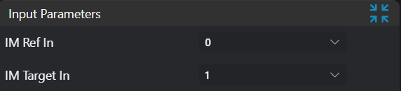
Input Parameters
| Parameter | Range | Default Value | Description | Illustration |
|---|---|---|---|---|
| Input Reference Image | 0-8 | 0 | Reference image input IM number | |
| Input Target Image | 0-8 | 1 | Target image input IM number |
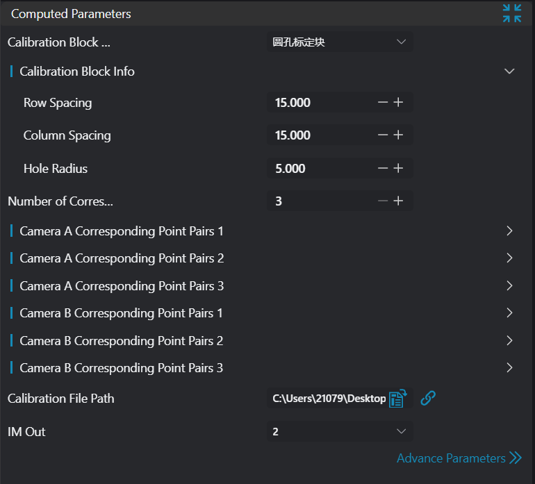
Calculation Parameters
| Parameter | Range | Default Value | Description | Illustration |
|---|---|---|---|---|
| Point Selection Mode | Manual/Automatic | Manual | In manual mode, points need to be selected manually, and selection positions must match preset positions on the calibration block. At least 5 non-coplanar point pairs are required, selection range includes vertices of the frustum and 4 vertices of the base upper surface; in automatic mode, input images containing only the calibration block are required, and the calibration block image must be complete. The algorithm will automatically calculate the 8 vertices of the frustum. | |
| Point Selection List | Only displayed in manual mode. Points A-L correspond to vertex positions on the calibration block as shown in the illustration. | 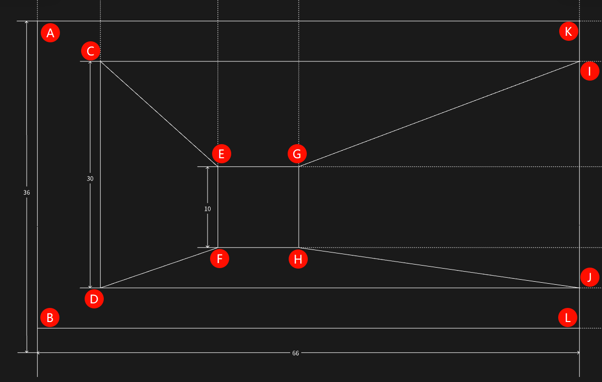 | ||
| Output Calibration File Path | Empty | Calibration file save path | ||
| Output Image | 0-8 | 0 | The IM number for image output. Displayed images are transformed target image and reference image |
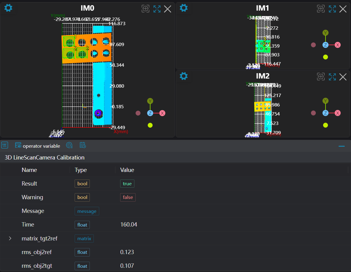
Output Parameters
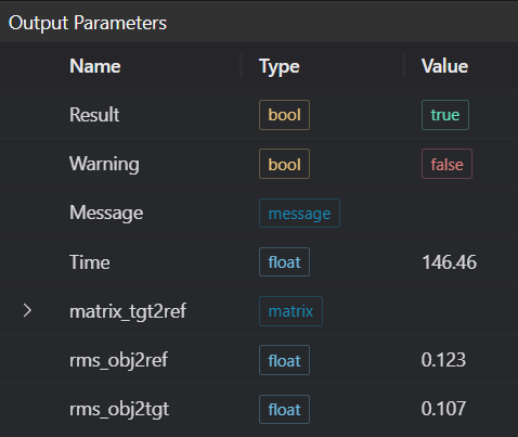
| Name | Type | Range | Description |
|---|---|---|---|
| Result | bool | true/false | true for success false for failure |
| Warning | bool | true/false | true indicates there is a warning false indicates there is none |
| Message | string | Outputs success, error, or warning information; if there is no error or warning, it is empty | |
| Time | float | Operator execution time, unit: ms | |
| matrix_tgt2ref | matrix | Calibration matrix from target camera coordinate system to reference camera coordinate system. | |
| rms_obj2ref | matrix | Root mean square error between corresponding points on calibration block after transformation and corresponding points on reference image. | |
| rms_obj2tgt | matrix | Root mean square error between corresponding points on calibration block after transformation and corresponding points on target image. | |
| rms_tgt2ref | matrix | Root mean square error between corresponding points on target image after transformation and corresponding points on reference image. |
Exception Troubleshooting
| No. | Exception Information | Corresponding Parameter | Solution |
|---|---|---|---|
| 1 | Input image is empty | Check if input image is empty | |
| 2 | Calibration file path parameter is empty | Select correct file path | |
| 3 | At least 3 points required for matrix calculation | Set at least 3 points | |
| 4 | Point pair count mismatch | Number of points set on reference image must equal number set on target image |
Example Introduction
This example calculates calibration matrices from target camera coordinate system to reference camera coordinate system through manual point selection mode and automatic point selection mode respectively.
Engineering Design
Manual Point Selection Mode
- Select 3
Load 3D Point Cloudoperators. - Select
Lua Scriptoperator. - Select 2
3D Line Scan Camera Calibrationoperators.
Automatic Point Selection Mode
- Select 3
Load 3D Point Cloudoperators. - Select 2
3D Line Scan Camera Calibrationoperators.
Tool Usage
Manual Point Selection Mode
Select 3
Load 3D Point Cloudoperators. Input calibration block images captured by 3 cameras into IM0, IM1, IM2 respectively in order.Select
Lua Scriptoperator, input corresponding point coordinates in camera 1, camera 2, and camera 3 images in the script, as follows:luaprintln('Hello AI-Vision!') -- Points on camera 1 SetPoint3D("1_C", 15.5,63.0799980164,-5.95093011856) SetPoint3D("1_D", 45.4799995422,63.3099975586,-5.33064985275) SetPoint3D("1_E", 28.8999996185,48.1399993896,4.03621006012) SetPoint3D("1_F", 38.3799972534,48.1299972534,4.19015979767) SetPoint3D("1_G", 28.7799987793,37.969997406,4.01133012772) SetPoint3D("1_H", 38.6399993896,38.2599983215,4.21365976334) SetPoint3D("1_I", 16.6999988556,3.37999987602,-5.81731987) SetPoint3D("1_J", 46.5799980164,3.42999982834,-5.53338003159) -- Points on camera 2 SetPoint3D("2_C", 6.33999967575,62.3099975586,-6.11768007278) SetPoint3D("2_D", 36.5,62.8599967957,-5.6080198288) SetPoint3D("2_E", 19.9200000763,47.6499977112,3.81477999687) SetPoint3D("2_F", 29.4200000763,47.3999977112,3.99586009979) SetPoint3D("2_G", 19.7799987793,37.6899986267,3.84138989449) SetPoint3D("2_H", 29.5999984741,37.8999977112,3.98522996902) SetPoint3D("2_I", 7.57999992371,2.72000002861,-6.00668001175) SetPoint3D("2_J", 37.3199996948,3.07999992371,-5.76390981674) -- Points on camera 3 SetPoint3D("3_D", 24.98, 62.549999, -5.75619) SetPoint3D("3_E", 8.44, 47.32, 3.68806) SetPoint3D("3_F", 17.9, 47.16, 3.86188) SetPoint3D("3_G", 8.26, 37.309998, 3.6232) SetPoint3D("3_H", 18.119999, 37.649998, 3.8217) SetPoint3D("3_J", 25.959999, 2.84, -5.93972)Select one
3D Line Scan Camera Calibrationoperator to calibrate between camera 1 and camera 2. Set both reference image point selection and target image point selection to manual mode. Bind 1_C to 1_J in reference image point selection list and 2_C to 2_J in target image point selection list. Set output calibration file path to ./calib_21.json. Set output image number to 3.Select one
3D Line Scan Camera Calibrationoperator to calibrate between camera 2 and camera 3. Set both reference image point selection and target image point selection to manual mode. Bind 2_D, 2_E, 2_F, 2_G, 2_H, 2_J in reference image point selection list and 3_D, 3_E, 3_F, 3_G, 3_H, 3_J in target image point selection list. Set output calibration file path to ./calib_32.json. Set output image number to 4.
Automatic Point Selection Mode
- Select 3
Load 3D Point Cloudoperators. Input calibration block images captured by 3 cameras into IM0, IM1, IM2 respectively in order. - Select one
3D Line Scan Camera Calibrationoperator to calibrate between camera 1 and camera 2. Set both reference image point selection and target image point selection to automatic mode. Set output calibration file path to ./calib_21.json. Set output image number to 3. - Select one
3D Line Scan Camera Calibrationoperator to calibrate between camera 2 and camera 3. Set both reference image point selection and target image point selection to manual mode. Set output calibration file path to ./calib_32.json. Set output image number to 4.