3D Height
Operator Function
Use the selected filtering method to calculate the height of the input region. Available height output options include minimum, maximum, mean, median, and percentile. 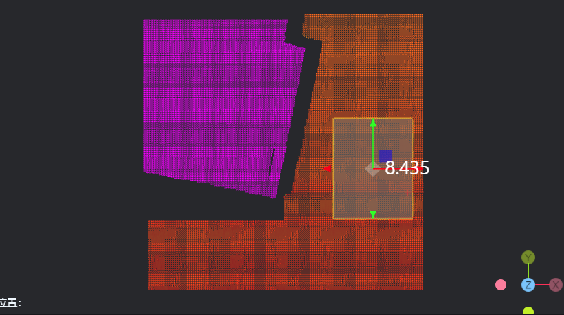
Parameter Introduction
Input Parameters

| Parameter | Range | Default Value | Description | Illustration |
|---|---|---|---|---|
| Input Image | 0-8 | 0 | The IM number for image input | |
Calculation Parameters
| Parameter | Range | Default Value | Description | Illustration |
|---|---|---|---|---|
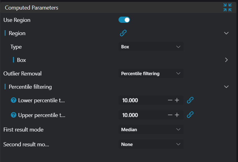
| Outlier Removal | Percentile Filter | Percentile Filter | Calculate high and low percentiles based on input percentage, only retaining point cloud that meets conditions between them | |
| Low Removal Percentage | 10.000 | Calculate low threshold in Z direction based on input percentage, remove all points below this threshold | 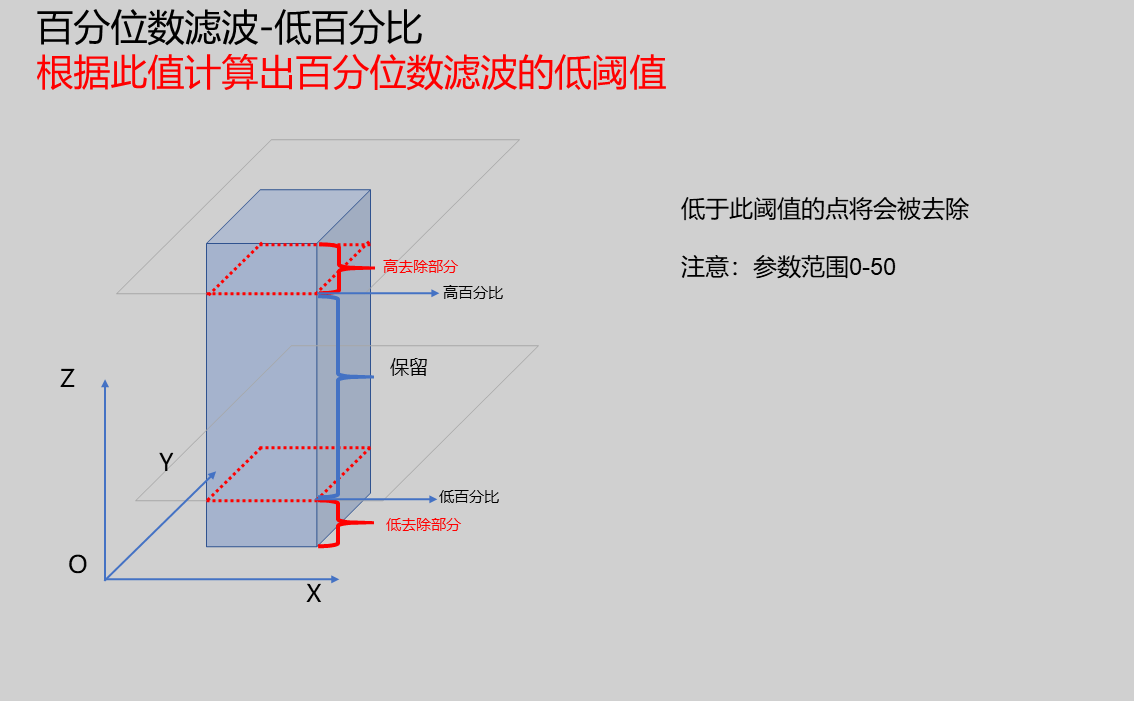 | |
| High Removal Percentage | 10.000 | Calculate high threshold in Z direction based on input percentage, remove all points above this threshold |  | |
| Height 1 Mode, Height 2 Mode | Minimum: Output minimum height of all points in region Maximum: Output maximum height of all points in region Mean: Output mean height of all points in region Median: Output median height of all points in region Percentile: Output height value at a% percentile, where a is the input percentage | |||
| Percentage 1, Percentage 2 | Only valid in percentile height mode. |
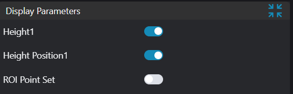
Result Display
| Parameter | Range | Default Value | Description | Illustration |
|---|---|---|---|---|
| Height 1 | true/false | false | Height 1 value information; if enabled, displayed in the image | |
| Height 2 | true/false | false | Height 2 value information; if enabled, displayed in the image | |
| Height Measurement Point 1 | true/false | false | Height 1 position point; if enabled, displayed in the image | |
| Height Measurement Point 2 | true/false | false | Height 2 position point; if enabled, displayed in the image | |
| ROI Point Set | true/false | false | Point set of ROI selected region; if enabled, displayed in the image |
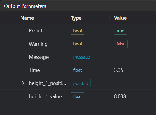
Output Parameters
| Name | Type | Range | Description |
|---|---|---|---|
| Result | bool | true/false | true for success false for failure |
| Warning | bool | true/false | true indicates there is a warning false indicates there is none |
| Message | string | Outputs success, error, or warning information; if there is no error or warning, it is empty | |
| Time | float | Operator execution time, unit:ms | |
| height_1_position_point | point3d | Height 1 position point coordinates | |
| height_1_value | float | Height 1 value | |
| height_2_position_point | point3d | Height 2 position point coordinates | |
| height_2_value | float | Height 2 value |
Exception Troubleshooting
| No. | Exception Information | Corresponding Parameter | Solution |
|---|---|---|---|
| 1 | The input value is {0}, invalid region type | Region Type | Only supports window2d, box, pointset |
| 2 | Region is empty | 1. Check if input point cloud is empty 2. Check if ROI region encloses any point cloud 3. Check if bound pointset is empty | |
| 3 | The input value is {0}, invalid height 1 mode | Height 1 Mode | Only supports Minimum, Maximum, Mean, Median, Standard deviation, Percentile, none |
| 4 | The input value is {0}, invalid height 2 mode | Height 2 Mode | Only supports Minimum, Maximum, Mean, Median, Standard deviation, Percentile, none |
| 5 | Failed to calculate height 1 | Check if high and low percentage ranges are correct; must be below 50 | |
| 6 | Failed to calculate height 2 | Check if high and low percentage ranges are correct; must be below 50 | |
| 7 | High and low percentages cannot both be 50% | Adjust high and low percentages; cannot both be 50 |
Example Introduction
Engineering Design
Select the
Load 3D Point Cloudtool to load the 3D point cloud image to be processed into IM0.Select the
3D Region Operationtool to select region for plane fitting.Select the
3D Plane Fittingtool, bind the region selected in the previous step, and fit the reference plane as the zero plane.Select the
3D Point Cloud Croptool to copy IM0 point cloud to IM1, IM2, IM3, IM4, IM5 respectively.
Tool Usage
Select the input image for operation; the image number must match the IM number where the image is located in the project.
Select the region type as Box, move the box to the position to be measured, enclosing the point cloud to be measured.
Usage Tips
- Use the ROI controller on the image window to drag or scale the box;
- Directly modify the start or end coordinates of the box in the calculation parameters to adjust the box position and size;
- Set parameters
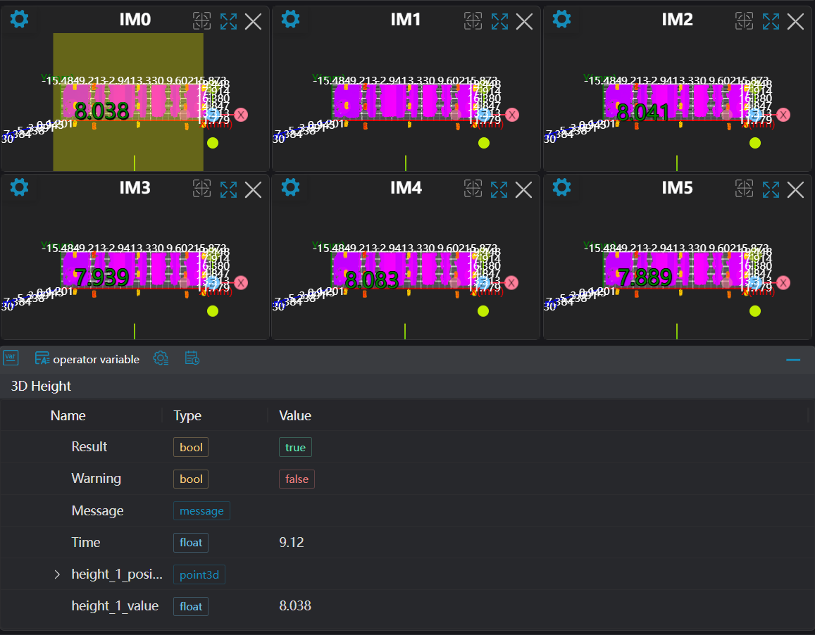
Select multiple 3D Height tools and set different height modes.
Check the content you want to display in the result display section
Click
Testto check if the image window and parameters meet expectationsIf there are no issues, click
Save, then run the operator in the run list to view the results in the corresponding IM