Adhesive Path Inspection - Segmentation
Operator Function
This operator measures whether the adhesive strip is broken, its width, height, and other parameters. It selects the input adhesive strip point cloud and outputs in global variables whether the adhesive strip meets requirements, width, and height information.
Note: The operator supports measuring ring-shaped, U-shaped single-connected adhesive paths. Before using the tool, appropriate downsampling can be applied to the adhesive path point cloud to improve detection efficiency
Parameter Introduction
Input Parameters

| Parameter | Range | Default Value | Description | Illustration |
|---|---|---|---|---|
| Input Image | 0-8 | 0 | The IM number for image input | |
Calculation Parameters
| Parameter | Range | Default Value | Description | Illustration |
|---|---|---|---|---|
| Use Region Parameter | true/false | false | If enabled, use Region as input; if disabled, use Input Image as input | |
| Region | 2D Window/2D Circular Window/2D Polygon Window/Box/Cylinder Box/Rotated Box/Point Set (Binding Only) | Box | Manually select appropriate ROI regionCan bind to select existing ROI regions | |
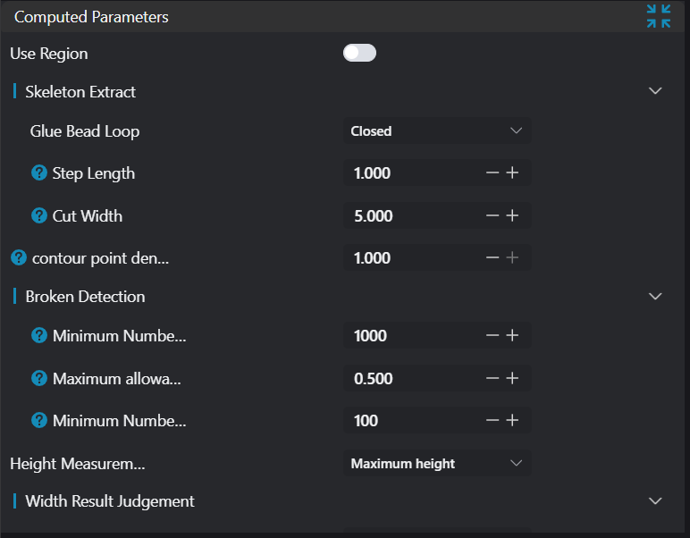
| Adhesive Path Loop | Open/Closed | Closed | Select the type of adhesive path loop to detect Open: As shown below, these are open adhesive paths where the path does not form a closed loop Closed: As shown below, these are closed adhesive paths where the path forms a closed loop | 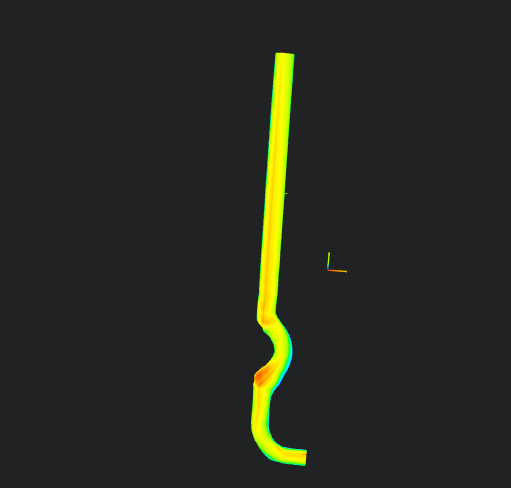 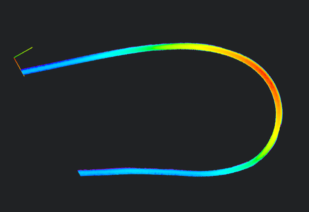  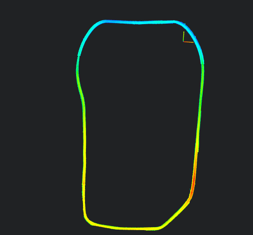 |
| Step Length | 1.000 | Spacing for extracting width/height | 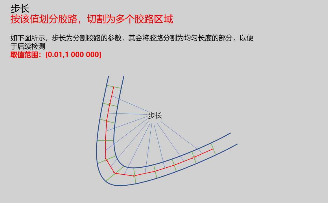 | |
| Cutting Width | 5.000 | Set the cutting width perpendicular to the adhesive path, This value is half of the actual cutting value | 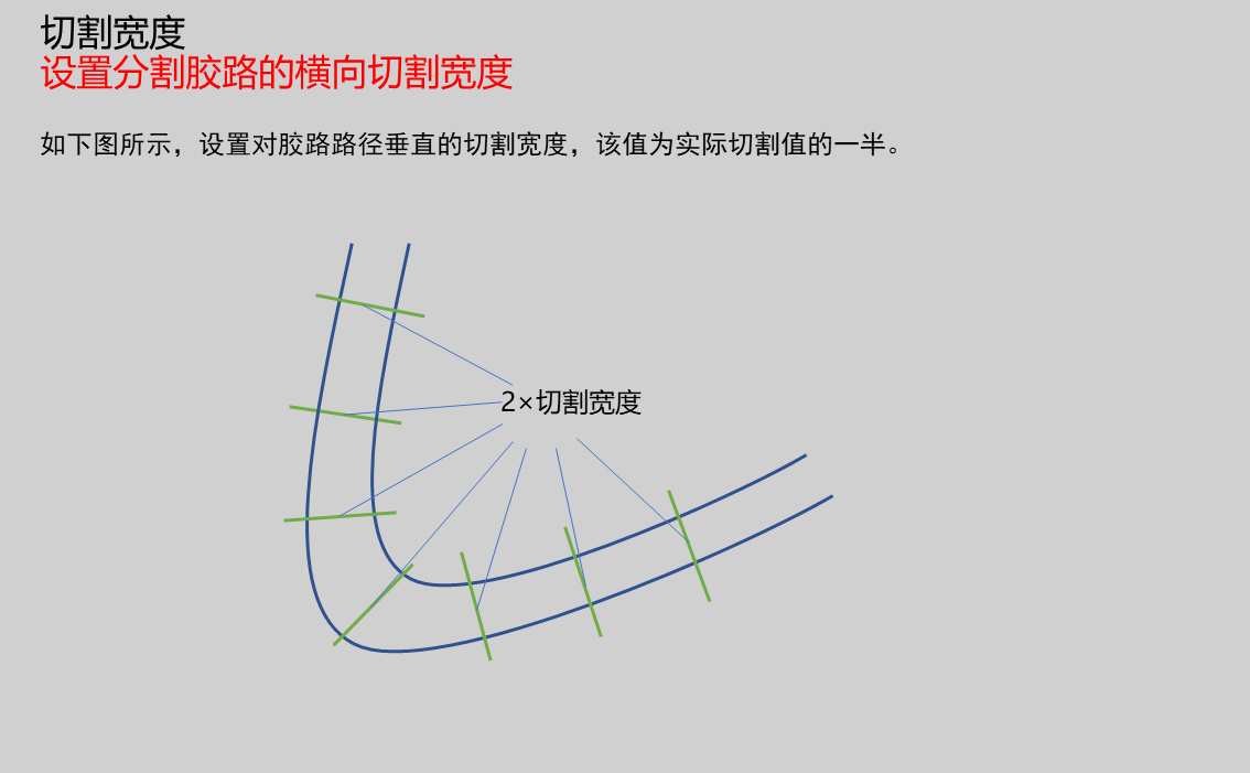 | |
| Center Point | Only enabled when Adhesive Path Loop is Open. Set the position of the adhesive path center point. Generally, the selected point should have connections to the adhesive path arranged sequentially clockwise or counterclockwisePosition: Input X, Y coordinates of center point | 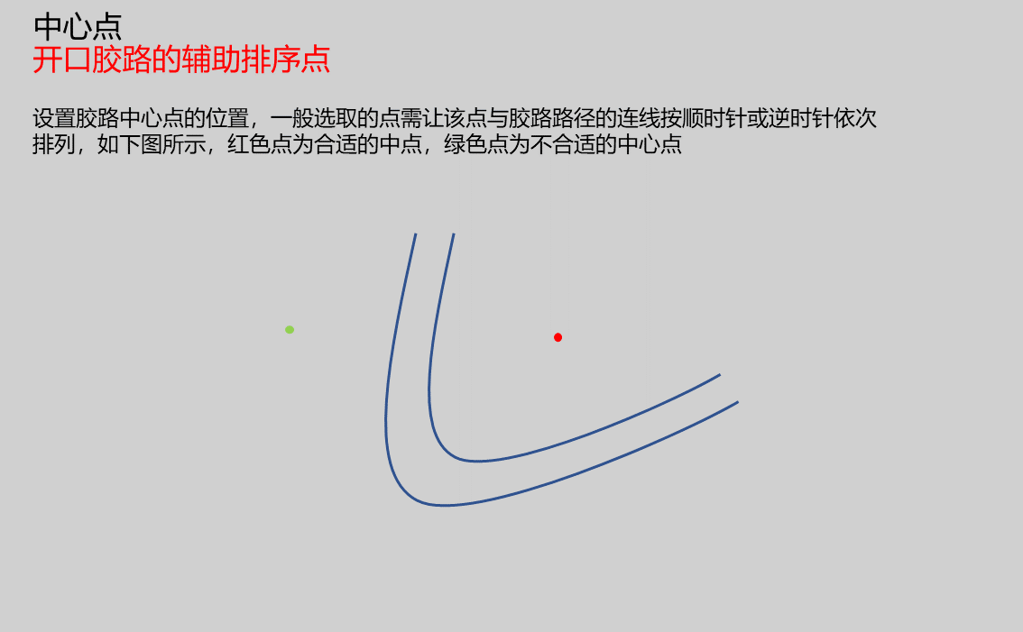 | ||
| Contour Density | 0.1-1 | 1.000 | Set the density for extracting the outer contour of the adhesive path. The value ranges from 0.1-1. Typically, higher values result in denser extracted contours. Higher density provides more accurate measurements, but excessively dense point cloud outer contours can also affect measurement accuracy. | 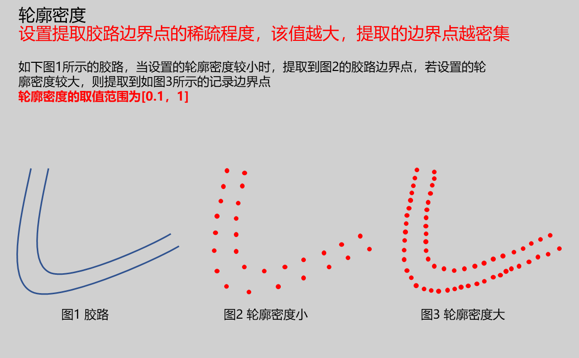 |
| Minimum Adhesive Points | 1000.000 | Points exceeding this value are considered adhesive point cloud | 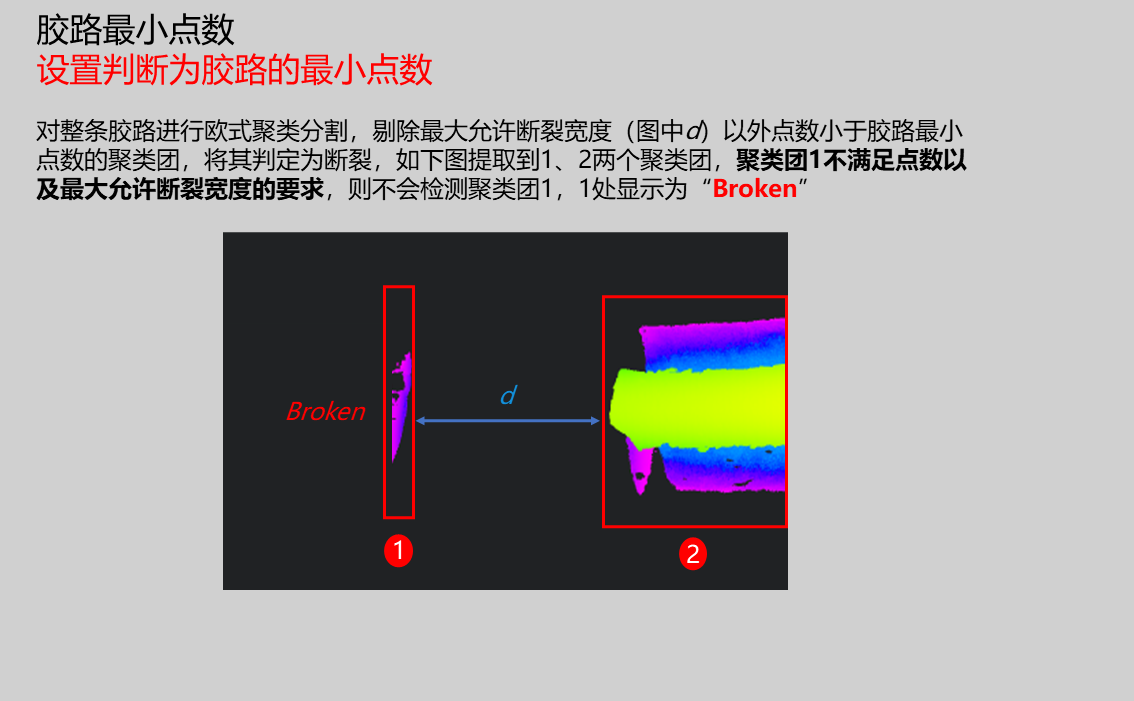 | |
| Maximum Allowable Break Width | 0.500 | Set intervals exceeding this value as gaps Note: Only recognized as break when point cloud is separated by this length | 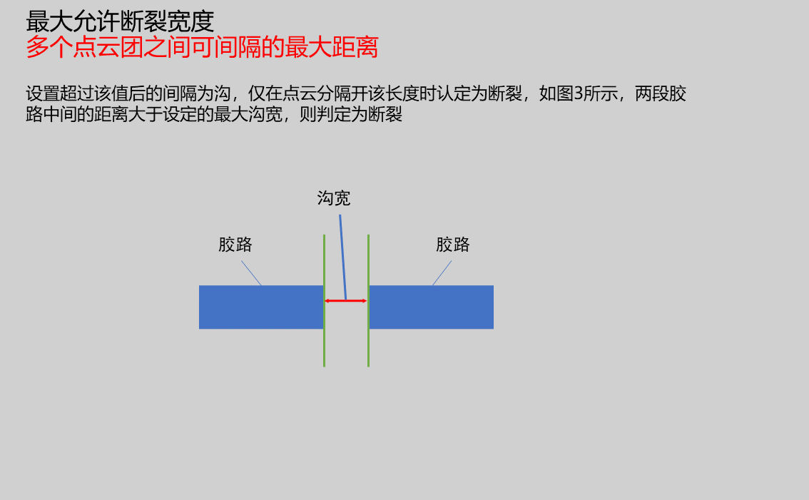 | |
| Minimum Segmentation Points | 50 | Set segmentation regions below this value as breaks | 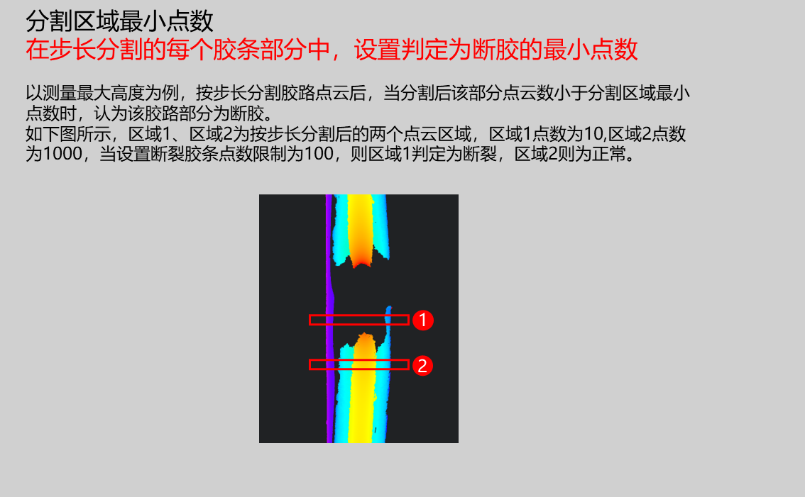 | |
| Height Measurement | Minimum Height/Maximum Height | Maximum Height | Minimum Height: Set search height as minimum height in region Maximum Height: Set search height as maximum height in region | |
| Minimum Width | 0.100 | Set the minimum width that meets requirements | ||
| Maximum Width | 1.000 | Set the maximum width that meets requirements | ||
| Judgment Mode | Any/Continuous | Any | Any: When any number of regional width values exceeds the set outlier count, judge as NG Continuous: When several consecutive regional width values exceed the set outlier count, judge as NG | |
| Outlier Count | 1 | Set to judge as NG when number of outlier values exceeds this value | ||
| Minimum Height | 0.100 | Set the minimum height that meets requirements | ||
| Maximum Height | 1.000 | Set the maximum height that meets requirements | ||
| Judgment Mode | Any/Continuous | Any | Any: When any number of regional height values exceeds the set outlier count, judge as NG Continuous: When several consecutive regional height values exceed the set outlier count, judge as NG | |
| Outlier Count | 1 | Set to judge as NG when number of outlier values exceeds this value | ||
| Projection Height | 5.000 | Set the height of the projection plane. The contour and width will be displayed on the plane at this height value. For example, if height h is set, the contour and width will be displayed on the Z=h plane.Note: When operator measurement values exceed the input range, red parameter values will be displayed at that measurement location | ||
| Resolution | 0.200 | Advanced parameter, downsamples input point cloud. Larger values result in faster processing but lower measurement accuracy. For better measurement results, set this value slightly larger than point spacing | 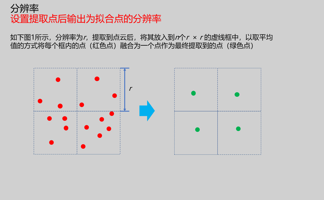 | |
| Filter Size | 3/5/7 | 5 | Advanced parameter, affects skeleton extraction accuracy. Larger filter sizes result in more blurred skeleton extraction |
Result Display
| Parameter | Range | Default Value | Description | Illustration |
|---|---|---|---|---|
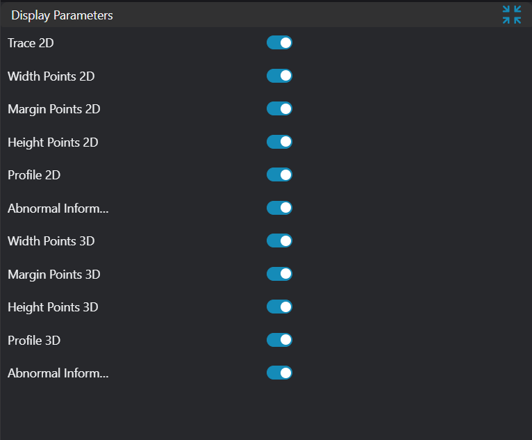
| Height Measurement Points | true/false | false | Height points of each region after adhesive path segmentation by step length, display in image if enabled | |
| Height Measurement Point Connections | true/false | false | Connect height points of each region sequentially along adhesive path direction after segmentation by step length, display in image if enabled | |
| Contour | true/false | false | Outer contour line of adhesive path, display in image if enabled | |
| Width Measurement Line Segments | true/false | false | Width line segments of each region after adhesive path segmentation by step length, display in image if enabled | |
| Width | true/false | false | Width values of each region after adhesive path segmentation by step length, display in image if enabled | |
| Height | true/false | false | Height values of each region after adhesive path segmentation by step length, display in image if enabled | |
| Break Information | true/false | false | Display Broken information at break locations when detected, display in image if enabled | |
| ROI Point Set | true/false | false | Only effective when Use Region Parameter is enabled. ROI selected region point set, display in image if enabled |
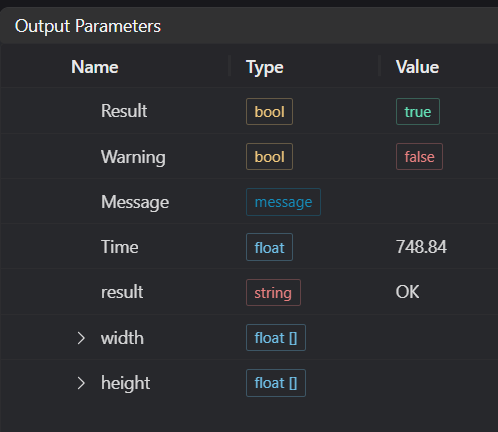
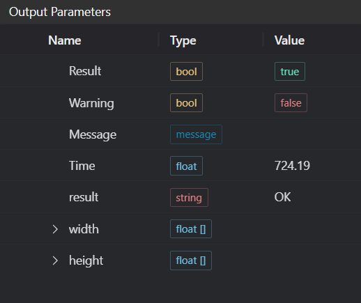
Output Parameters
| Name | Type | Range | Description |
|---|---|---|---|
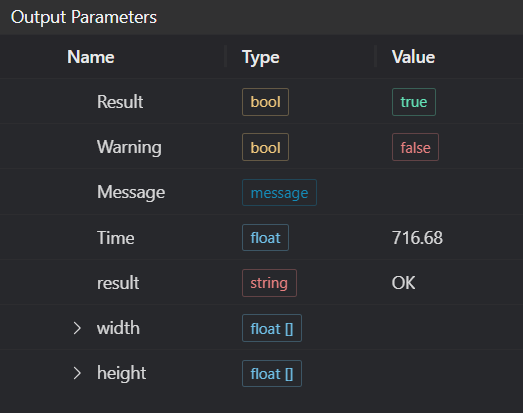
| Result | bool | true/false | true for success false for failure |
| Warning | bool | true/false | true indicates a warning false indicates none |
| Message | string | Output success, error, or warning messages. Empty if no error or warning | |
| Time | float | Operator execution time, unit: ms | |
| result | string | Output adhesive path inspection result | |
| width | float[] | Output height values of each region after adhesive path segmentation by step length | |
| height | float[] | Output width values of each region after adhesive path segmentation by step length |
Tip
For more detailed explanations of parameter types, please refer to... (add link to parameter type introduction)...
Exception Troubleshooting
| No. | Exception Information | Corresponding Parameter | Solution |
|---|---|---|---|
| 1 | Input region type is {0}, invalid region type | Region Type | Region input type must be one of: 2D Window/2D Circular Window/2D Polygon Window/Box/Cylinder Box/Rotated Box/Point Set |
| 2 | Region is empty | 1. Check if selection is empty 2. Check if point set is empty | |
| 3 | Input point cloud is empty | Confirm if IM contains valid points. If no valid points, load point cloud or switch to IM with valid points | |
| 4 | Adhesive path not found | 1. Check if minimum adhesive points is too small 2. Check if resolution is too large 3. Check if step length is suitable for point cloud 4. Check if cutting width is appropriate | |
| 5 | Resolution too small | Appropriately increase resolution | |
| 6 | Input adhesive path loop type is {0}, invalid adhesive path loop type | Adhesive Path Loop Type | Select adhesive path loop type as Open/Closed |
| 7 | Input height measurement mode is {0}, invalid height mode | Height Mode | Select height mode as Measure Maximum Height/Measure Minimum Height |
| 8 | Failed to segment boundary points | Appropriately increase contour density/increase maximum points | |
| 9 | Input width judgment parameters invalid | Appropriately adjust width judgment parameters | |
| 10 | Input width judgment mode is {0}, invalid width judgment mode | Width Judgment Mode | Select mode as Any/Continuous |
| 11 | Input height judgment parameters invalid | Appropriately adjust height judgment parameters | |
| 12 | Input height judgment mode is {0}, invalid height judgment mode | Height Judgment Mode | Select mode as Any/Continuous |
| 13 | Input width judgment upper/lower limits invalid | Width judgment upper limit should be greater than or equal to lower limit | |
| 14 | Input height judgment upper/lower limits invalid | Height judgment upper limit should be greater than or equal to lower limit | |
| 15 | Input polygon vertex count is less than 3, cannot form polygon | Add 2D polygon window vertices so vertex count is at least three |
Example Introduction
Engineering Design
Select
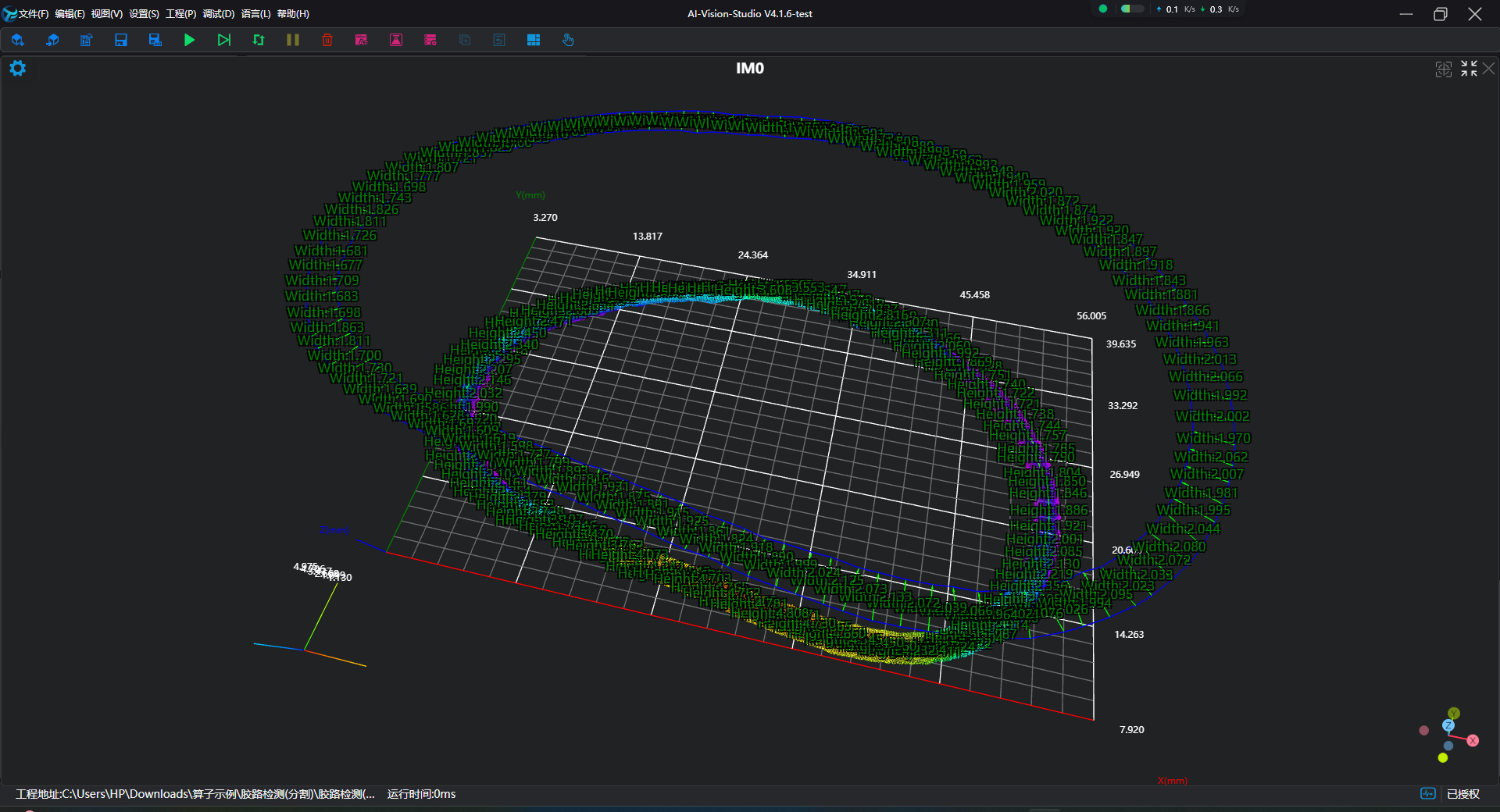
Load Point Cloudtool to load the requiredClosed Adhesive Pathpoint cloud image into IM0;Select
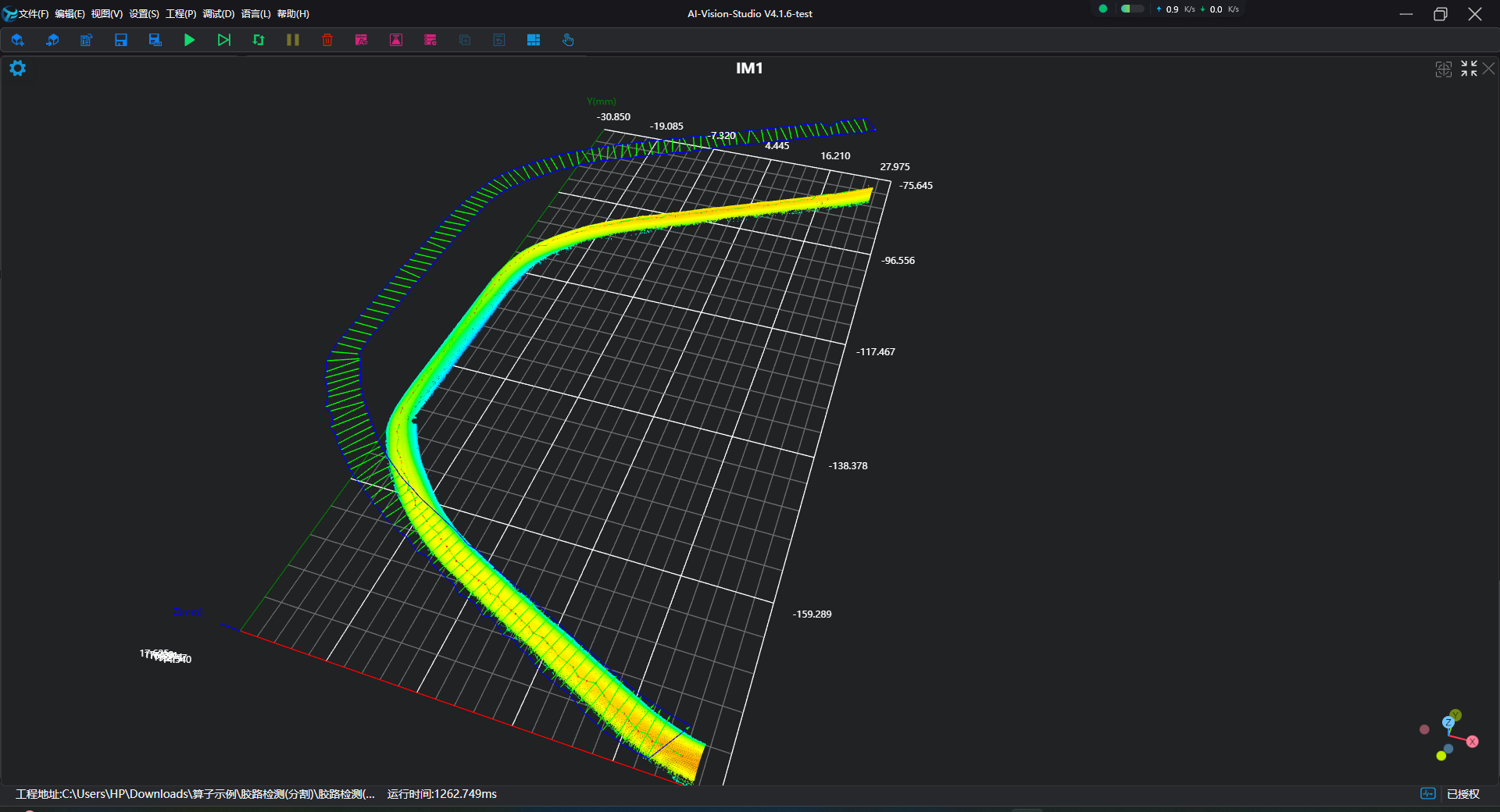
Load Point Cloudtool to load the requiredOpen Adhesive Pathpoint cloud image into IM1;Select
Adhesive Path Inspection - Segmentationtool.
Tool Usage
Select input image for operation. Image number must match IM number where image is located in project.
Either disable Use Region Parameter or enable Region and select region type as Box, then move box to target position to surround point cloud to be measured.
Usage Tips
- Use ROI controller on image window to drag or scale box;
- Directly modify box start or end coordinates in calculation parameters to adjust box position and size.
Set parameters.
Check desired display content in Result Display section.
Click
Testto check if image window and parameters meet expectations.If everything is correct, click
Save, then run operator in run list. View results in corresponding IM.