Battery Cover Flatness and Height Measurement
Project Background
Measurement Background
With the rapid development of new energy vehicles, consumer electronics, and other fields relying on high-performance battery systems, the quality requirements for battery components are increasingly stringent. As a key component in the battery structure, the flatness and height accuracy of the battery cover are directly related to the battery's safety performance, sealing effect, and overall assembly quality. Any slight deviation may lead to serious issues such as internal short circuits and leakage of the battery, thereby affecting product reliability and user safety.
Therefore, to ensure that every factory-delivered battery meets the highest quality standards, manufacturers need to introduce a precise and efficient detection system for the flatness and height of battery covers. This system aims to achieve strict monitoring of key dimensional parameters of battery covers through automated means, ensuring product consistency and reliability.
Camera Selection
Shenshi SR7080
Measurement Items
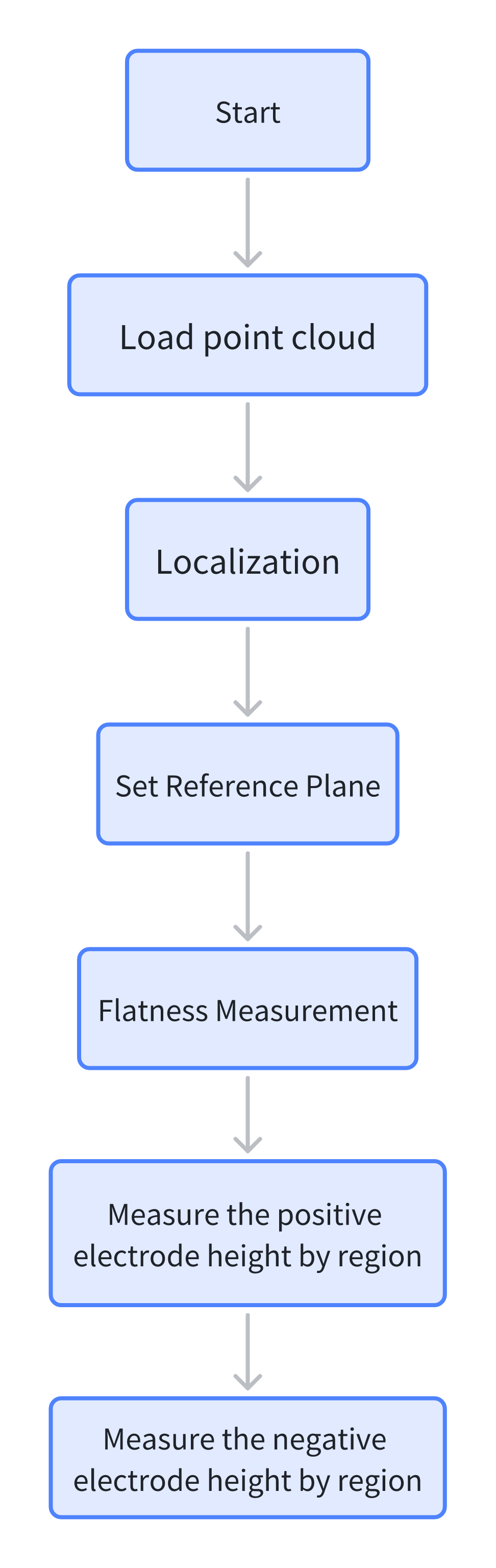
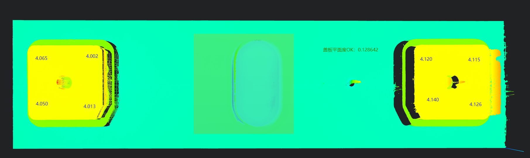
Flatness of the battery cover surface and heights of the positive and negative electrodes
Solution
AI-Vision first locates the point cloud image, then determines the reference plane of the battery surface to measure the surface flatness, and finally measures the heights of the positive and negative electrodes respectively.
Design Concept
Execution Effect Display
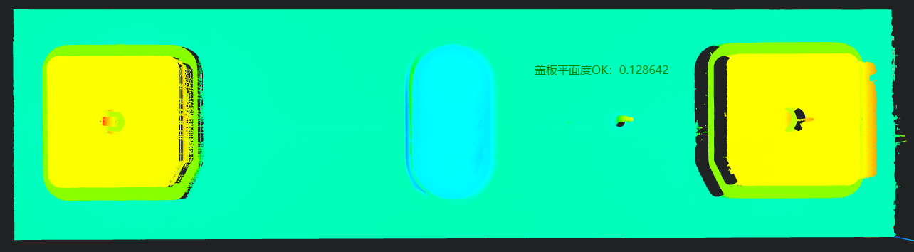
- Project Result Display
- Detection Results
- Detection Results
Project Process
1. Initialization
Use the Load Point Cloud tool to load the point cloud image to be processed. 
2. Preprocessing
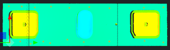
Position Adjustment
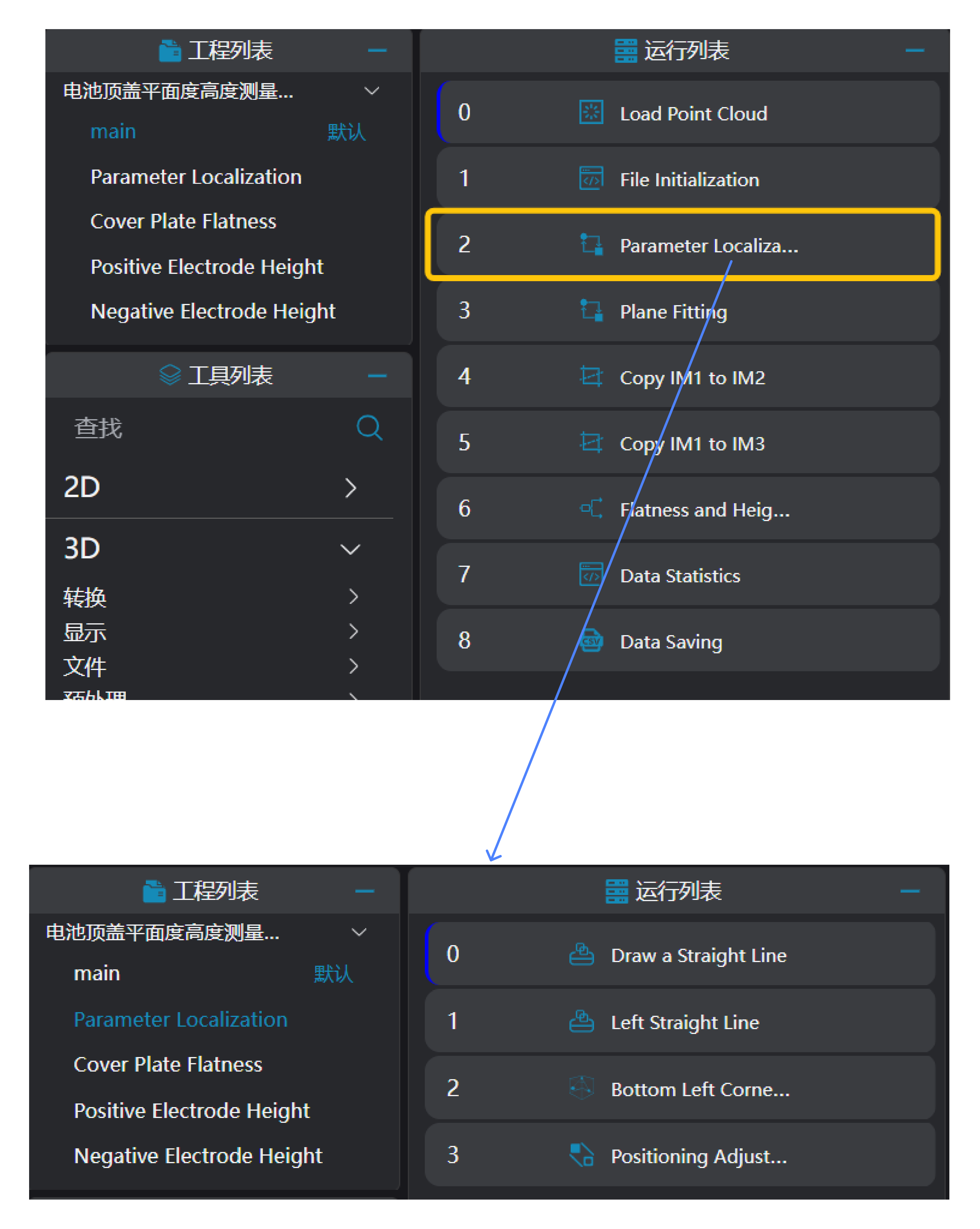
Use the
3D Square Probetool to find the lower edge line and left edge line of the battery point cloud respectively.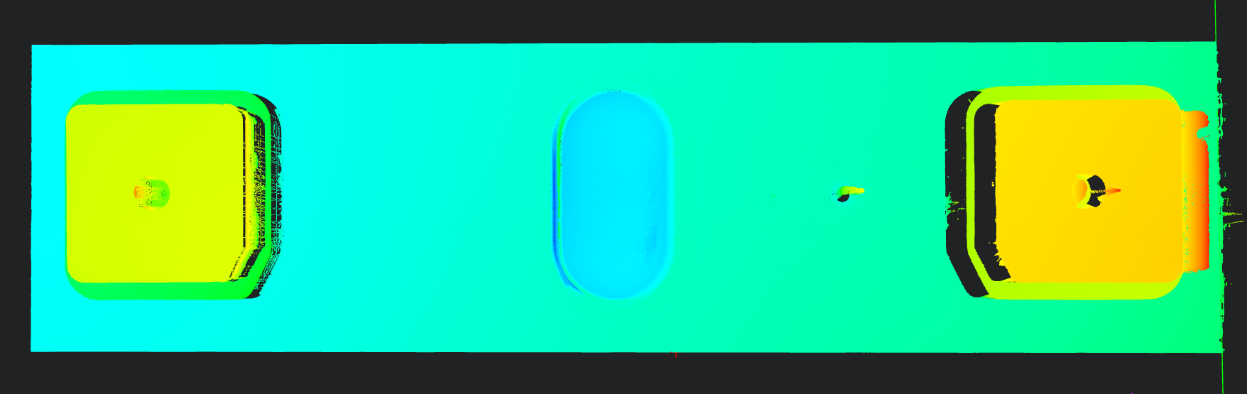
Use the
3D Geometric Intersectiontool to calculate the intersection point of the two lines detected in the previous step.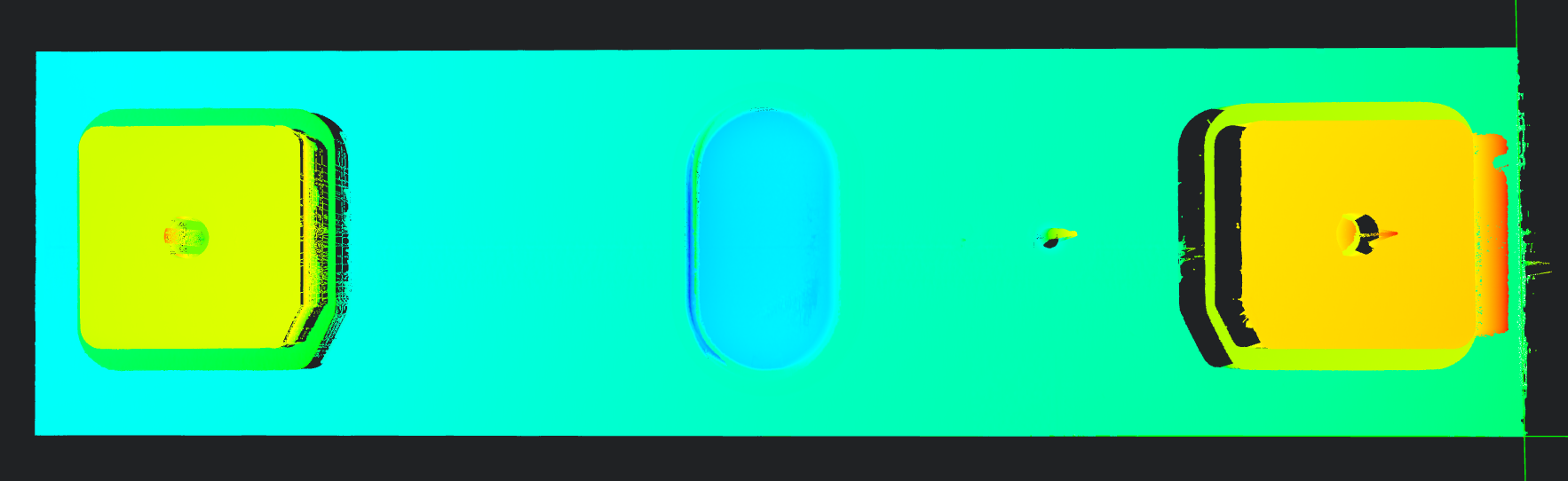
Use the
3D Position Adjustmenttool to adjust the positioning to the intersection point of the two lines.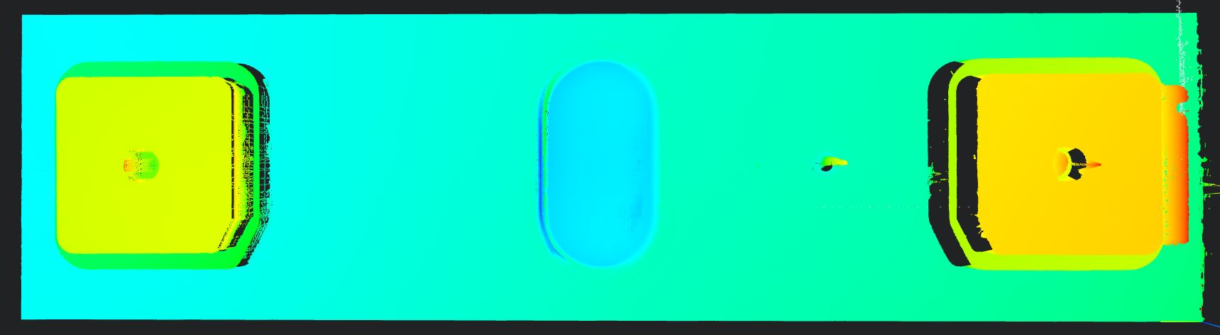
Plane Fitting
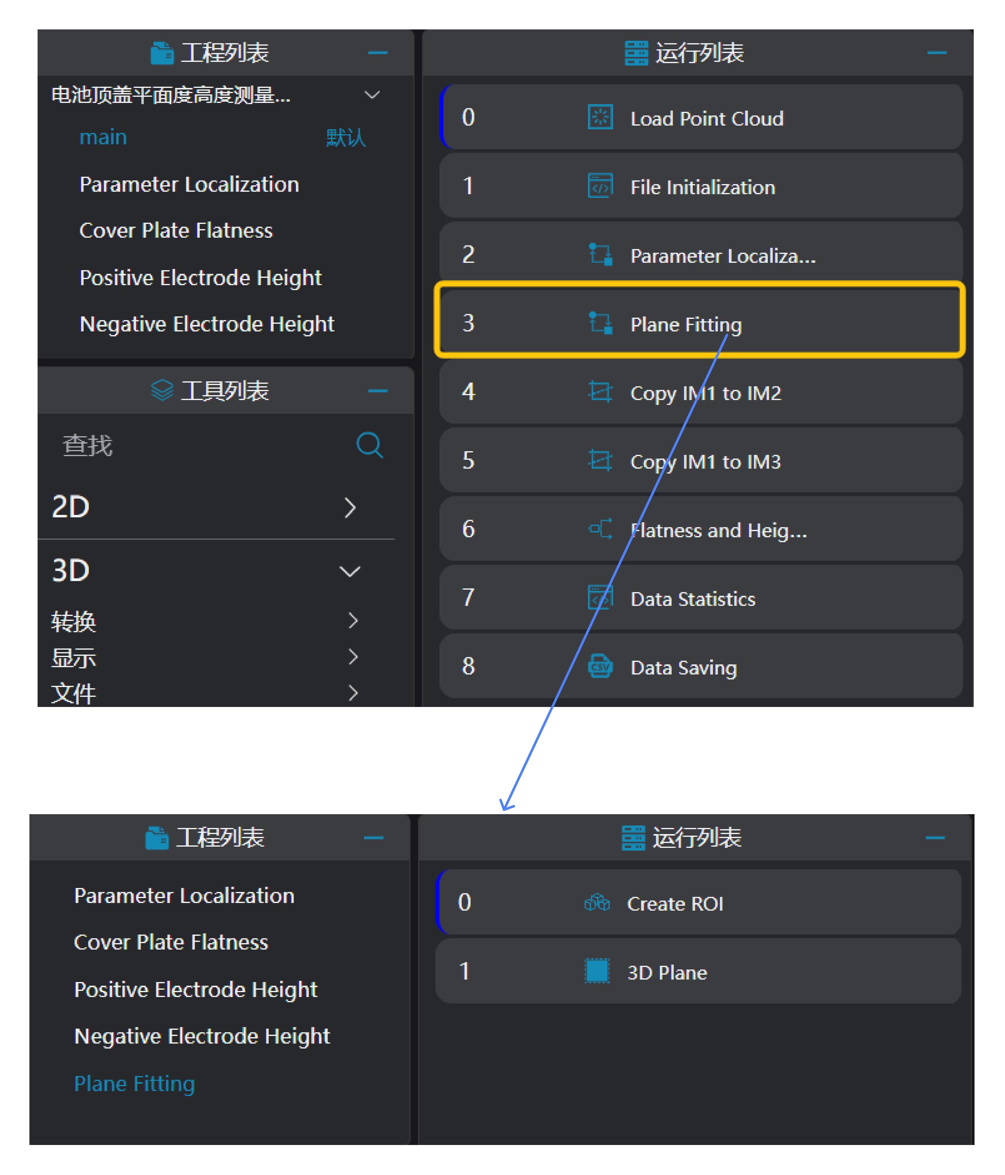
Use the
Create ROItool to frame the reference area ROI.Use the
3D Planetool to fit a plane based on the ROI area selected by theCreate ROItool and set it as the zero plane.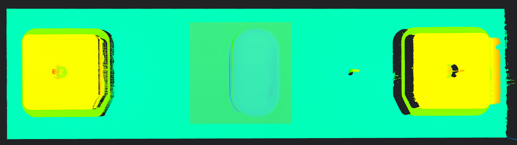
Copy IM for Different Subprogram Calls
Copy IM1 to IM2 and IM3: Copy IM1 to IM2 and IM3 for measuring the cover flatness and heights respectively.
Tip
When using parallel subprogram calls, each subprogram needs to be executed in a different IM.
3. Cover Flatness and Height Measurement
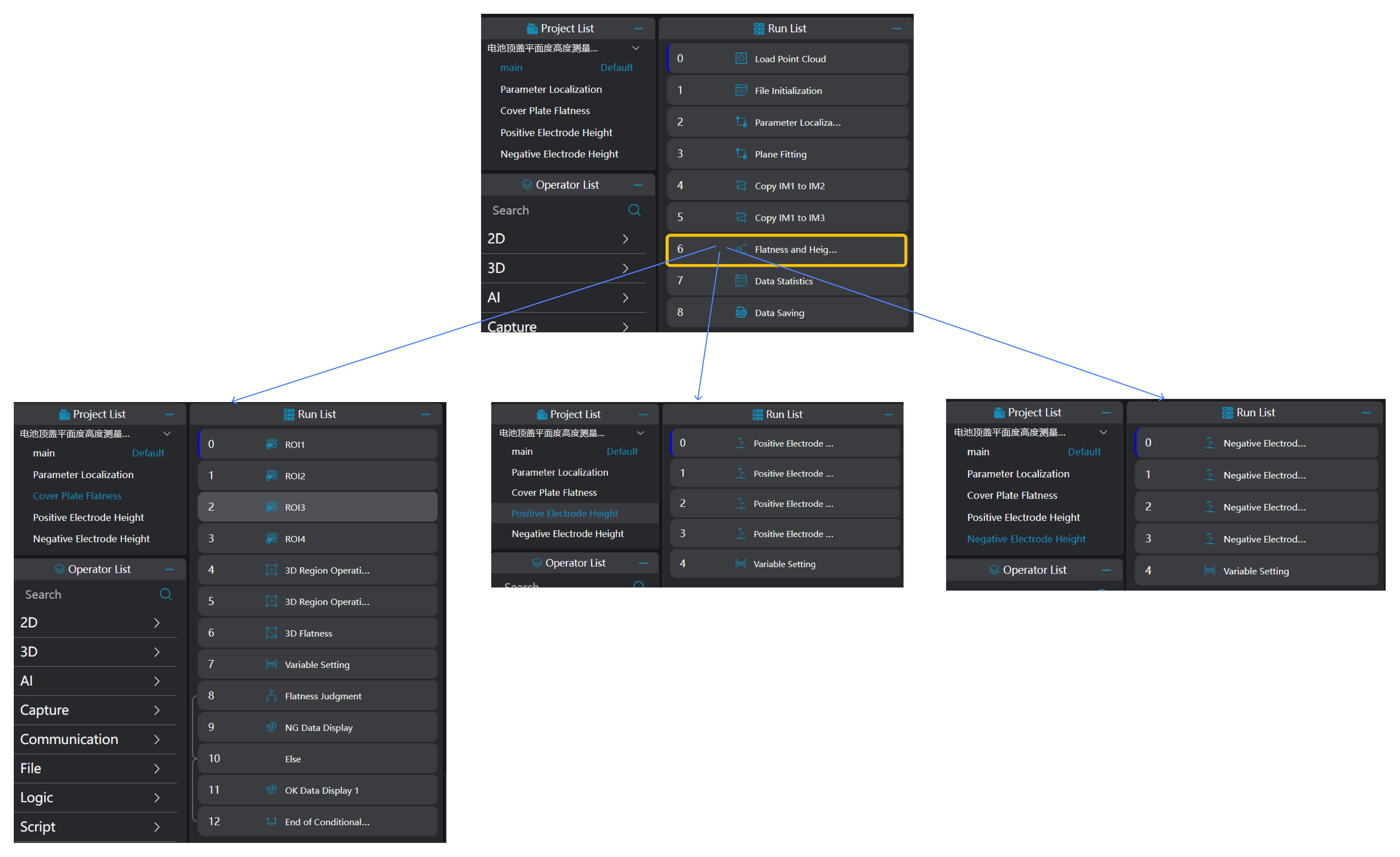
Cover Flatness Measurement
Use the
Create ROI Arraytool to frame the ROIs of the positions where flatness needs to be measured according to the drawing.Use the
3D Region Operationtool to bind the ROIs framed by theCreate ROI Arraytool and integrate them into a single region.Use the
3D Flatnesstool to bind the region output by the3D Region Operationtool and calculate the flatness information.Use the
Variable Settingtool to add a compensation value to the flatness value and set it to a global variable.
Tip
The compensation value is added according to specific requirements; Global variables need to be manually set in the global variables section;
- Use the
Conditional Branchtool to determine whether the flatness information is within the threshold. Display OK or NG data respectively when it is within the threshold or not.