Position Tolerance of Circular Holes on Brake Pad Support Plate
Engineering Background
Measurement Background
Dimensional inspection of brake pad support plates ensures product quality and safety, complies with industry standards, and guarantees interchangeability and reliability. Precise measurement prevents manufacturing deviations and enhances market competitiveness. Strict inspection helps optimize design, ensuring each component meets optimal performance standards and safeguarding the safety of the braking system.

Camera Selection
LMI Laser Line Scan Camera Gocator2350
Measurement Items
- Length of the brake pad support plate
- Distance from large circular holes to the edge
- Distance from large circular holes to the connecting line of the two lower holes
Inspection Requirements
- Static repeatability ≤ 0.003mm
- Dynamic repeatability ≤ 0.01mm
Solution
AI-Vision adopts the 3D Hole Tool to output the center coordinates of each hole, followed by distance calculation. It features simple operation, zero coding, and fast deployment.
Design Concept
Implementation Effect Display
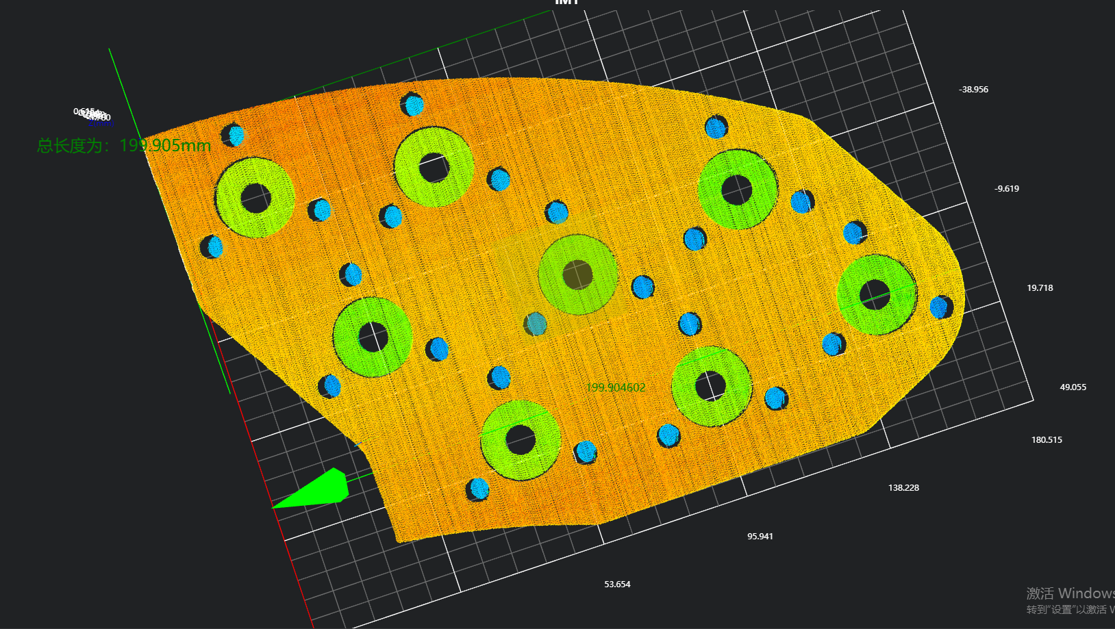
- Project Result Display
- Length Result
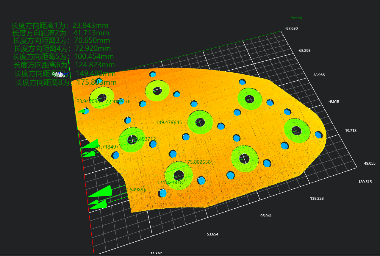
- Position Result of Circular Holes in Length Direction
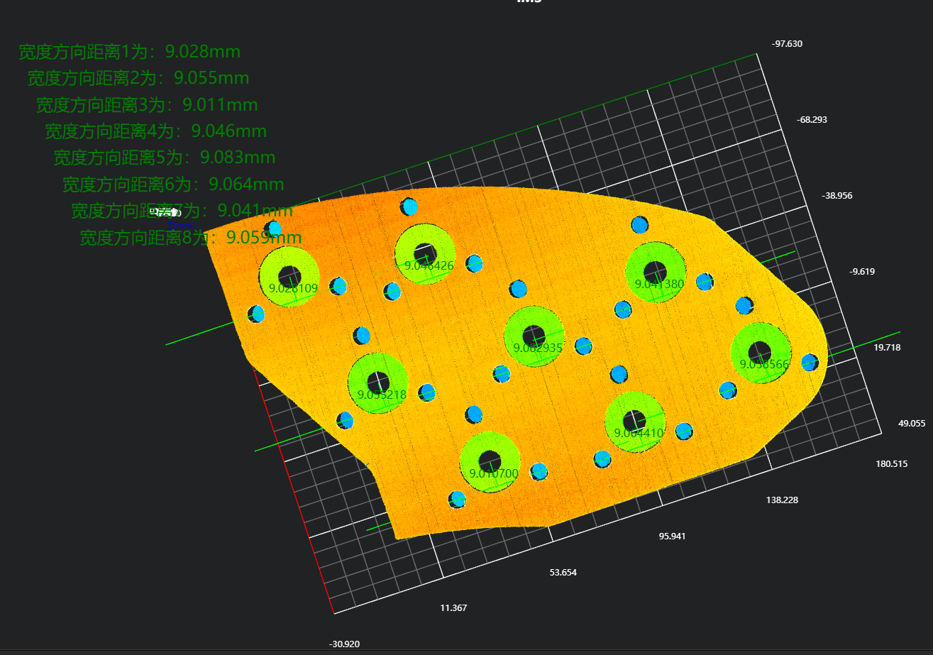
- Position Result of Circular Holes in Width Direction
- Length Result
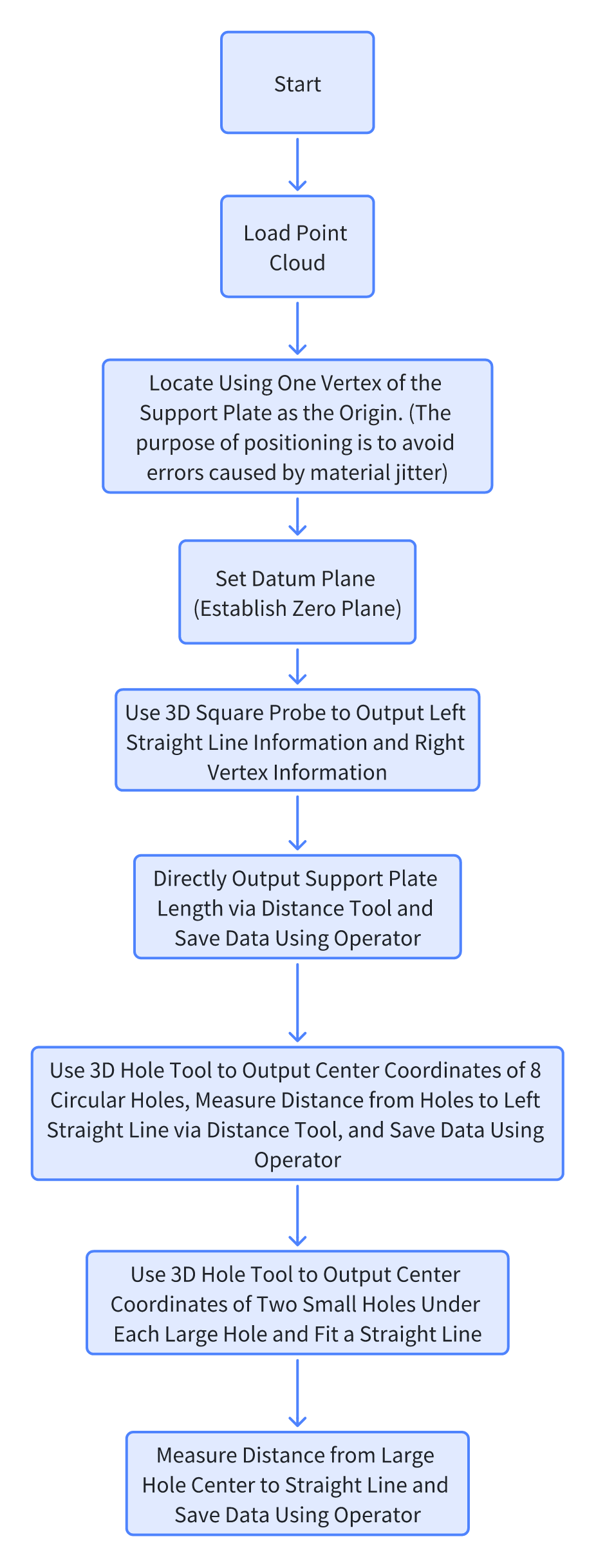
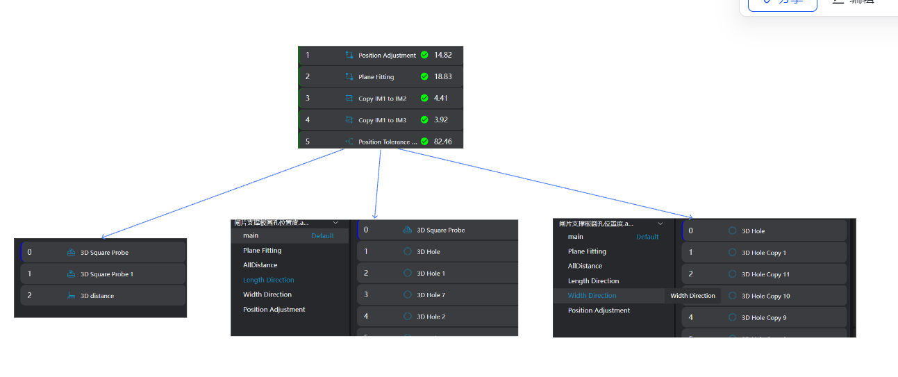
Project Process
1. Initialization
- Use the
Load Point Cloud Toolto load the point cloud image to be processed.
2. Preprocessing
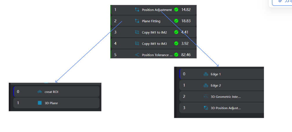
Position Adjustment
Use the
3D Square Probe Toolto obtain two edges of the workpiece.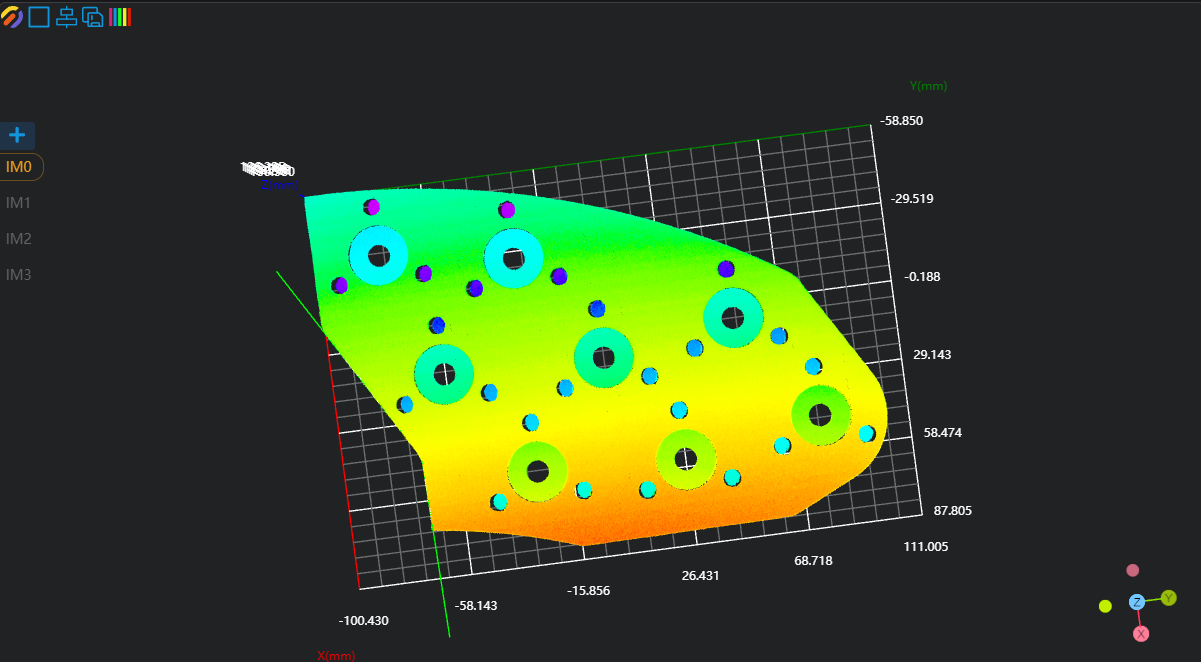
Use the
3D Geometric Intersection Tool, bind the two edges output by the operator variables in the previous step as input geometries, and output the intersection point of the two lines.Use the
3D Position Adjustment Tool, bind the line intersection point output by the operator variable in the previous step as the new origin, and adjust the point cloud position.
Plane Fitting
Use the
3D Region Toolto select the area for plane fitting.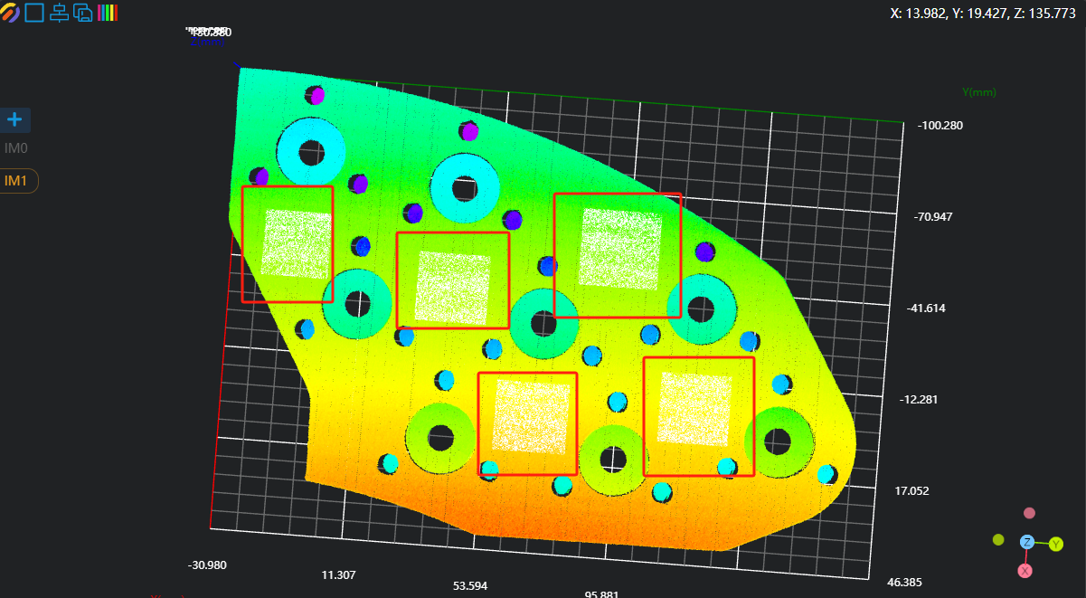
Use the
3D Plane Tool, bind the variable area output by the operator in the previous step as the input area, fit the plane, and set it as the zero plane.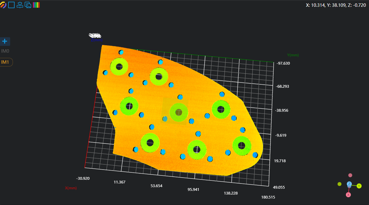
Copy IM for Different Subprogram Calls
Crop IM1 to IM2 and IM3 respectively for length and width measurement.
Note
When calling subprograms in parallel, each subprogram needs to be executed in a different IM.
3. Measurement of Length and Position Information
Overall Length Measurement
Use the
3D Square Probe Toolto find the left straight line and the right vertex respectively.Use the
3D Distance Tool, bind the line and point output in the previous step as Geometry 1 and Geometry 2, and run to obtain the distance from the right vertex to the left straight line.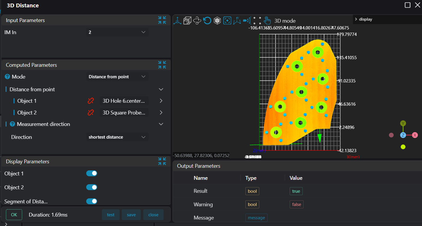
Position Information in Length Direction
Use the
3D Square Probe Toolto find the left straight line.Use eight
3D Hole Toolsto output the center position information of 8 large circular holes.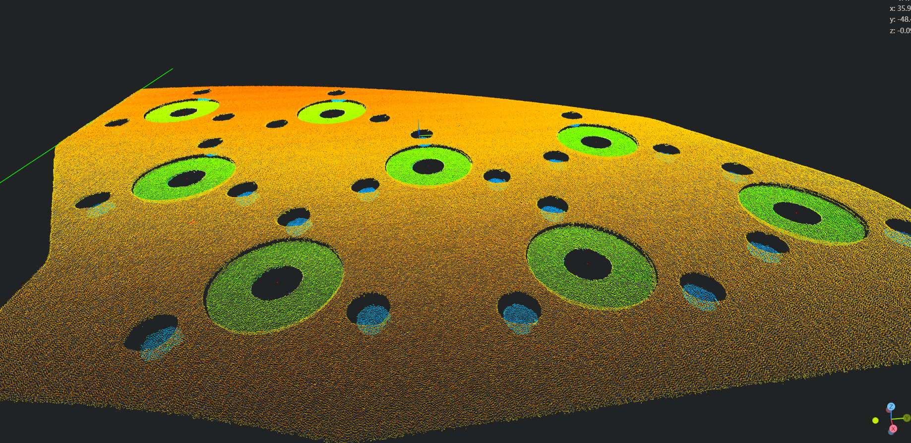
Use the
3D Distance Tool, bind the straight line and the center positions of the circular holes as Geometry 1 and Geometry 2, and calculate the distances from the 8 circular holes to the left straight line respectively.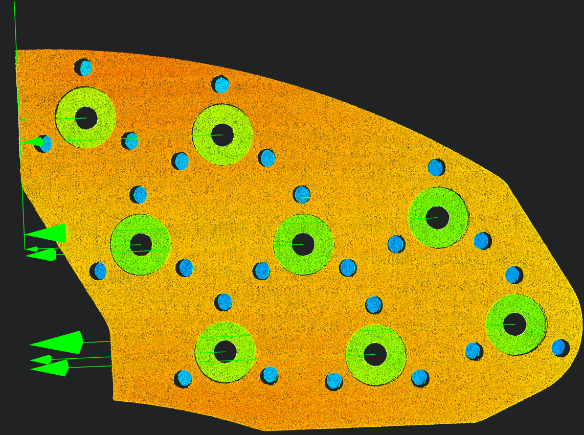
Position Information in Width Direction
Use the
3D Hole Toolto output the center information of 16 small holes (two small holes under each of the 8 large circular holes).Use the
3D Distance Tool, bind the two small hole centers as Geometry 1 and Geometry 2, and measure the distance between the centers of the two small holes under the large circular hole.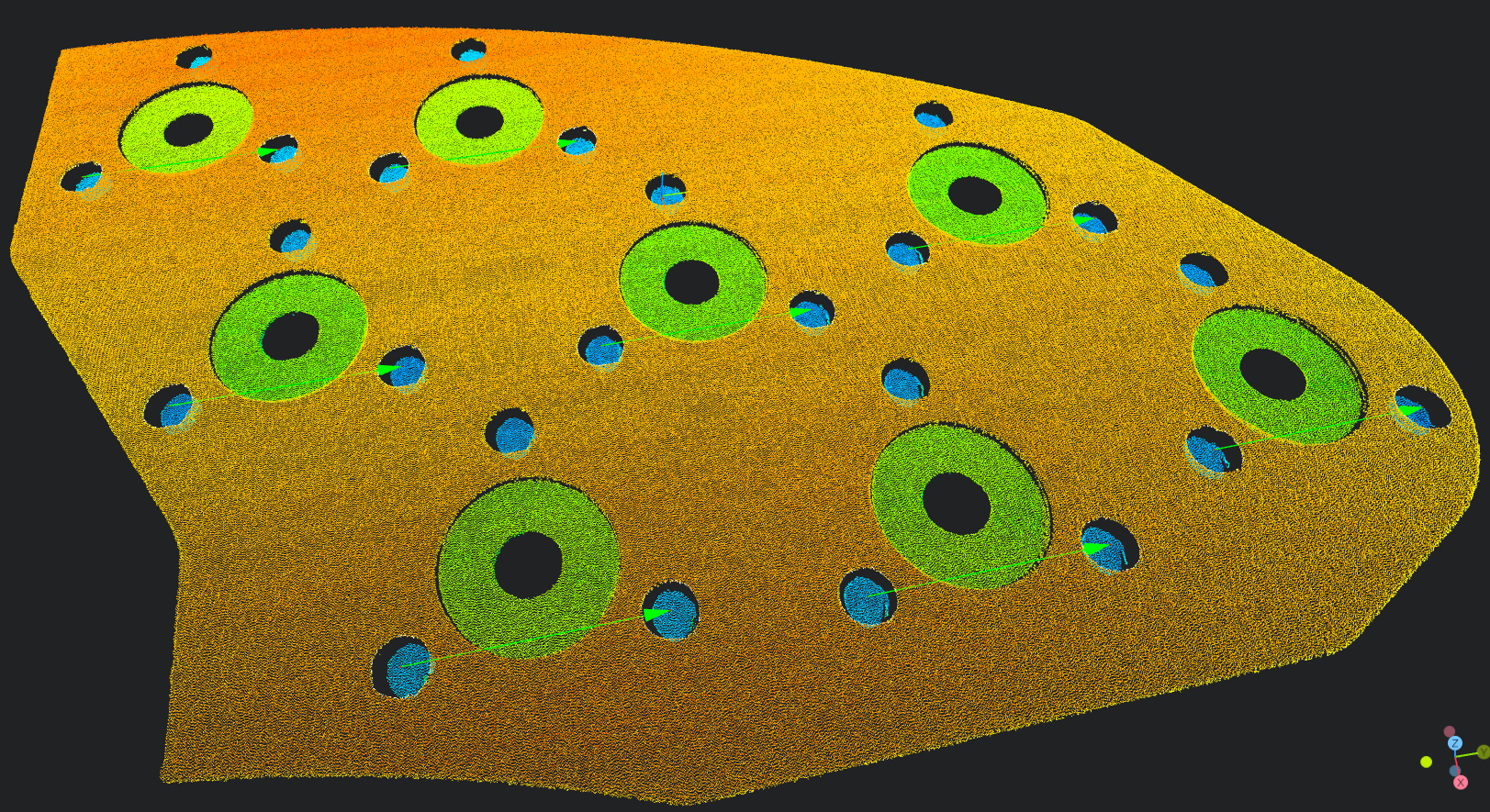
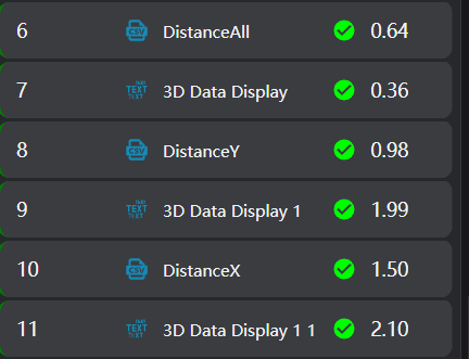
4. Data Saving
Select the Write to CSV operator.
- Bind the operator variables output in the previous step (total length of the brake pad, lengths of 8 large circular holes, widths of 16 circular holes). Select the
3D Data Displayoperator to display the data.