3D Coplanarity - Regression Plane Method
Operator Function
Use the regression plane method to calculate coplanarity deviationInput needs to bind several point cloud arrays to be measured
Principle Explanation:
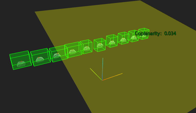
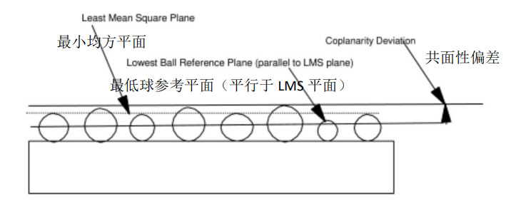
- Extract the highest points of each terminal point cloud
- Use the least squares method to determine the best fitting plane for all terminal vertices as the least mean square plane
- Calculate the plane parallel to the least mean square plane and passing through the lowest vertex as the lowest sphere reference plane
- The least mean square plane is parallelly offset to the terminal vertex showing the maximum vertical distance. The distance from the offset least mean square plane to the terminal farthest from the offset least mean square plane is the component's coplanarity deviation
Parameter Introduction
Input Parameters

| Parameter | Range | Default Value | Description | Illustration |
|---|---|---|---|---|
| Input Image | 0-8 | 0 | IM number for image input | |
Calculation Parameters
| Parameter | Range | Default Value | Description | Illustration |
|---|---|---|---|---|
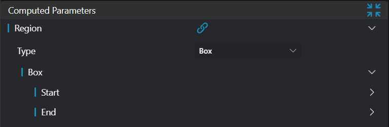
| Region | 2D Window/2D Circular Window/2D Polygon Window/Box/Cylindrical Box/Rotated Box/Point Set (binding only) | Box | Manually select appropriate ROI regionCan bind to select existing ROI region |
Result Display
| Parameter | Range | Default Value | Description | Illustration |
|---|---|---|---|---|
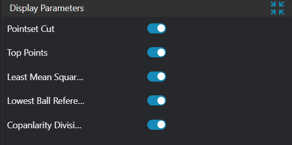
| Point Set | true/false | false | Input point set. If enabled, display in the image | |
| Vertices | true/false | false | Highest points of each input point cloud. If enabled, display in the image | |
| Least Mean Square Plane | true/false | false | Least mean square plane fitted from all vertices. If enabled, display in the image | |
| Lowest Sphere Reference Plane | true/false | false | Plane parallel to the least mean square plane and passing through the lowest vertex. If enabled, display in the image | |
| Coplanarity Deviation | true/false | false | Calculated coplanarity value. If enabled, display in the image |
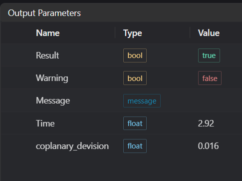
Output Parameters
| Name | Type | Range | Description |
|---|---|---|---|
| Result | bool | true/false | true for success, false for failure |
| Warning | bool | true/false | true indicates a warning, false indicates no warning |
| Message | string | Output success, error, or warning messages. Empty if no error or warning | |
| Time | float | Operator execution time, unit: ms | |
| coplanarity_deviation | float | Coplanarity |
Tip
For more detailed explanations of parameter types, please refer to Type Definitions
Exception Troubleshooting
| No. | Exception Information | Corresponding Parameter | Solution |
|---|---|---|---|
| 1 | Input point cloud is empty | Confirm if IM contains valid points. If no valid points, load point cloud or switch to IM with valid points | |
| 2 | Input region type is {0}, invalid region type | Region Type | Region input type must be one of: 2D Window/2D Circular Window/Box/Cylindrical Box/Rotated Box/Point Set |
| 3 | Input valid regions are {0}, at least 4 valid regions required | Region Count | Check if input ROI selects at least 4 point clouds |
| 4 | Input region number {0} is empty | Region Number | Check if these region numbers select point clouds |
Example Introduction
Engineering Design
Select the
Load Point Cloudtool to load the required 3D point cloud image to IM0.Select the
Create ROItool to select the point clouds needed as input.Select the
3D Coplanarity - Regression Plane Methodtool, set different output types.
Tool Usage
Select the input image for the operation. The image number must match the IM number where the image is located in the project.
Select the region type as Box, move the box to the position to be measured, enclosing the point cloud to be tested.
Usage Tips
- Use the ROI controller on the image window to drag or scale the box;
- Directly modify the box's start or end point coordinates in the calculation parameters to adjust the box position and size;
Set the parameters.
Check the content you want to display in the result display section.
Click
Testto check if the image window and parameters meet expectations.If there are no issues, click
Save. Run the operator in the run list, and then view the running results in the corresponding IM.