3D Coplanarity - Datum Plane Method
Operator Function
Use the datum plane method to calculate coplanarity deviation
Principle Explanation:
- Extract the highest points of each terminal point cloud
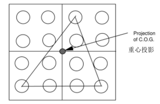
- Determine three terminal vertices exhibiting the maximum vertical distance (the terminal triangle defining the datum plane must contain the projection of the centroid to form a valid datum plane. If the plane is not considered valid, the next terminal with the maximum vertical distance will be considered as a candidate terminal to form a valid datum plane)
- Calculate the datum plane from the three vertices
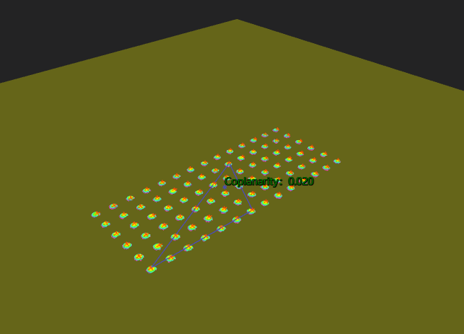
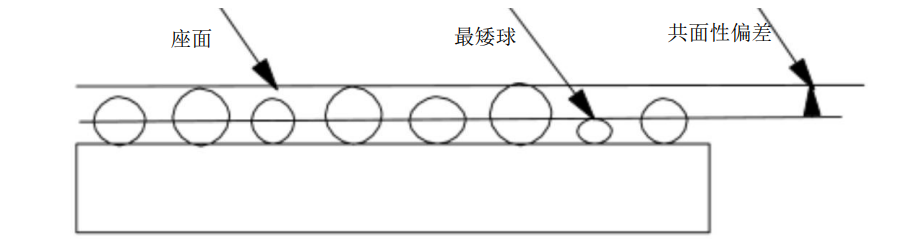
- The coplanarity deviation requires calculating the distance from the datum plane to each terminal vertex, where the maximum measured value is the coplanarity deviation:
Parameter Introduction
Input Parameters

| Parameter | Range | Default Value | Description | Illustration |
|---|---|---|---|---|
| Input Image | 0-8 | 0 | IM number for image input | |
Calculation Parameters
| Parameter | Range | Default Value | Description | Illustration |
|---|---|---|---|---|
| Region | 2D Window/2D Circular Window/2D Polygon Window/Box/Cylindrical Box/Rotated Box/Point Set (binding only) | Box | Manually select appropriate ROI regionCan bind to select existing ROI region | |
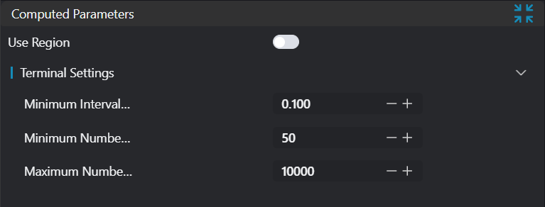
| Terminal Settings | Set parameters for terminal segmentation | |||
| Minimum Terminal Spacing | 0.0-1000000.0 | 0.1 | Minimum spacing to distinguish different terminals | |
| Minimum Points Per Terminal | 1-1000000 | 100 | Limit the minimum number of points in terminal point cloud | |
| Maximum Points Per Terminal | 1-1000000 | 10000 | Limit the maximum number of points in terminal point cloud |
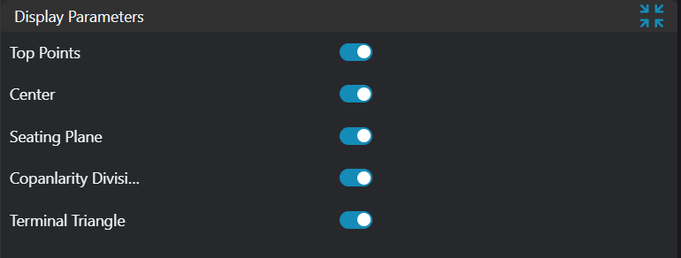
Result Display
| Parameter | Range | Default Value | Description | Illustration |
|---|---|---|---|---|
| Vertices | true/false | false | Highest points of each input point cloud. If enabled, display in the image | |
| Center | true/false | false | Centroid of all terminal point clouds. If enabled, display in the image | |
| Datum Plane | true/false | false | Plane formed by three qualified terminal vertices. If enabled, display in the image | |
| Coplanarity Deviation | true/false | false | Calculated coplanarity value. If enabled, display in the image | |
| Vertex Triangle | true/false | false | Triangle formed by three qualified terminal vertices |
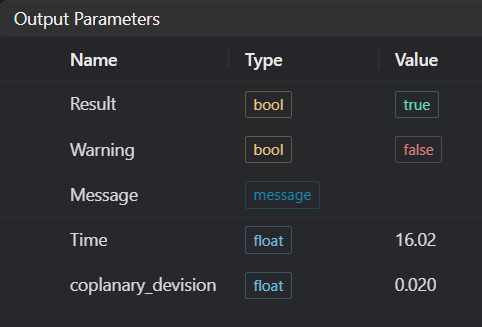
Output Parameters
| Name | Type | Range | Description |
|---|---|---|---|
| Result | bool | true/false | true for success, false for failure |
| Warning | bool | true/false | true indicates a warning, false indicates no warning |
| Message | string | Output success, error, or warning messages. Empty if no error or warning | |
| Time | float | Operator execution time, unit: ms | |
| coplanarity_deviation | float | Coplanarity |
Tip
For more detailed explanations of parameter types, please refer to Type Definitions
Exception Troubleshooting
| No. | Exception Information | Corresponding Parameter | Solution |
|---|---|---|---|
| 1 | Input point cloud is empty | Confirm if IM contains valid points. If no valid points, load point cloud or switch to IM with valid points | |
| 2 | Input region type is {0}, invalid region type | Region Type | Region input type must be one of: 2D Window/2D Circular Window/Box/Cylindrical Box/Rotated Box/Point Set |
| 3 | Region is empty | Check if input ROI selects at least 4 point clouds | |
| 4 | Number of detected terminals is {0}, at least 4 terminals required | Region Count | Check input point cloud or terminal setting parameters: terminal point limits or minimum terminal spacing |
| 5 | Input polygon vertex count is less than 3, cannot form polygon | Add 2D polygon window vertices so that vertex count is at least three | |
| 6 | No set of terminal vertices meets requirements | - | |
| 7 | Input terminal point limit is invalid | Set upper limit of terminal points to be greater than or equal to lower limit |
Example Introduction
Engineering Design
Select the
Load Point Cloudtool to load the required 3D point cloud image to IM0.Select the
3D Coplanarity - Datum Plane Methodtool, set different output types.
Tool Usage
Select the input image for the operation. The image number must match the IM number where the image is located in the project.
Bind the point cloud arrays to be measured.
Set the parameters.
Check the content you want to display in the result display section.
Click
Testto check if the image window and parameters meet expectations.If there are no issues, click
Save. Run the operator in the run list, and then view the running results in the corresponding IM.