3D Cylinder Fitting
Operator Function
Perform cylinder fitting on the input point cloud to obtain the fitted cylinder parameters: top and bottom center coordinates and cylinder radius (for better fitting results in a relatively short time, it is recommended that the point cloud contains 1000-100000 points)
Parameter Introduction
Input Parameters

| Parameter | Range | Default Value | Description | Illustration |
|---|---|---|---|---|
| Input Image | 0-8 | 0 | IM number for image input | |
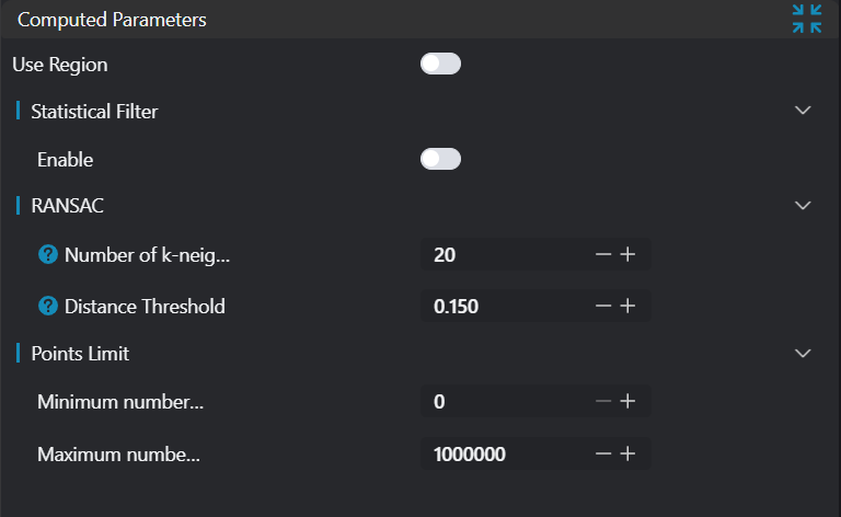
Calculation Parameters
| Parameter | Range | Default Value | Description | Illustration |
|---|---|---|---|---|
| Region | 2D Window/2D Circular Window/2D Polygon Window/Box/Cylindrical Box/Rotated Box/Point Set (binding only) | Box | Manual selection: Set the ROI region for cylinder fitting > Note: Ensure the ROI center point is inside the circle. Can bind to select existing ROI region | |
| Statistical Filter | true/false | false | Apply statistical filtering to the input point cloud | |
| Standard Deviation Multiple Threshold | 0.1-10 | 0.150 | Input parameter n, any point exceeding n times the standard deviation from the mean will be considered an outlier and removed | |
| Neighborhood Points | 3-500 | 100 | Number of neighbor points to consider during filtering (this number must be less than the number of input point cloud points) | |
| K-Nearest Neighbors | 3-500 | 20 | When calculating the normal of a point in the point cloud, the number of surrounding points to search. If the set search number is too large, it may introduce points far from the current point, leading to inaccurate estimation; if the set value is too small, it may ignore some adjacent points, also affecting the accuracy of normal estimation. |  |
| Distance Threshold | 0-10000 | 0.15 | When the distance between a data point and the fitted model is less than this threshold, the data point is considered an inlier (i.e., a point that fits the model); otherwise, it is considered an outlier (i.e., a point that does not fit the model) | 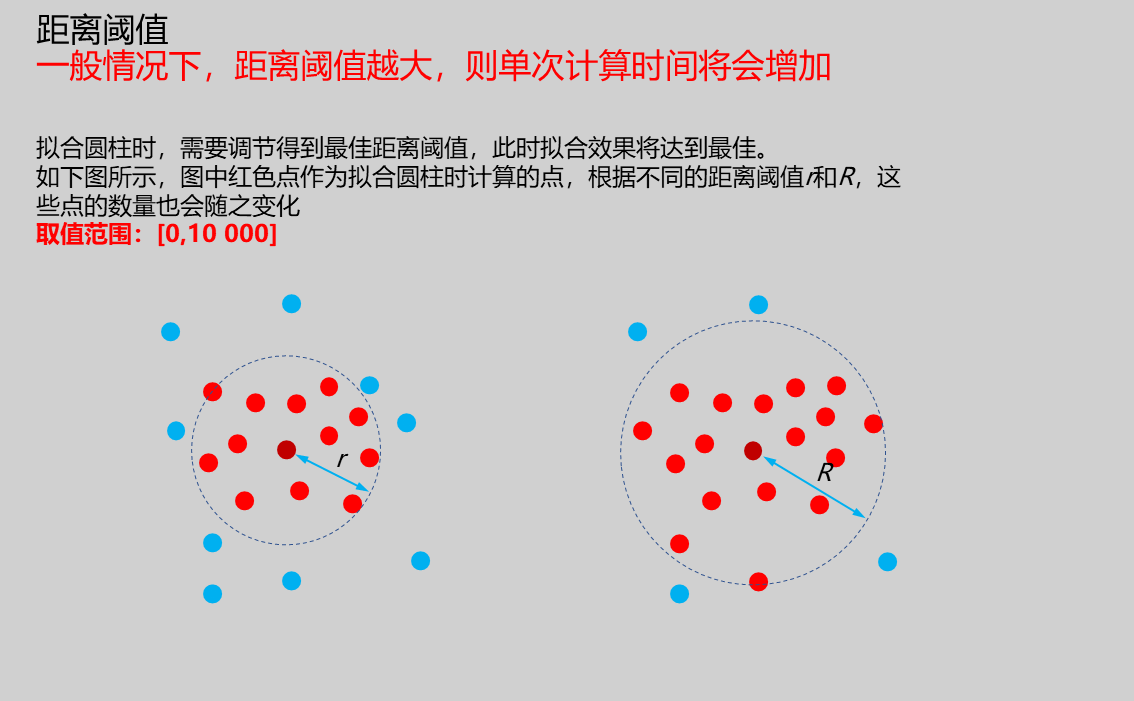 |
| Minimum Points | 0 | Set the minimum number of points in the input point cloud | ||
| Maximum Points | 1000000 | Set the maximum number of points in the input point cloud |
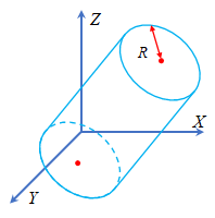
Note: As shown in the figure below, in the spatial coordinate system, a cylinder can be determined by the top and bottom center points and radius R.
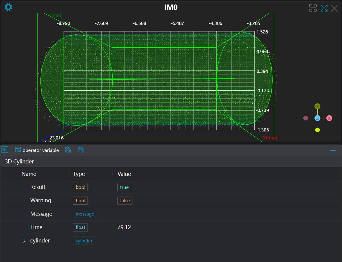
Result Display
| Parameter | Range | Default Value | Description | Illustration |
|---|---|---|---|---|
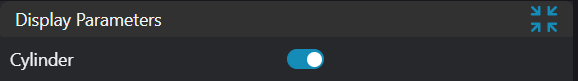
| Cylinder | true/false | false | If enabled, display the cylinder in the image | |
| ROI Point Set | true/false | false | Only effective when Use Region Parameters is selected. Region point set selected by ROI box. If enabled, display in the image |
Output Parameters
| Name | Type | Range | Description |
|---|---|---|---|
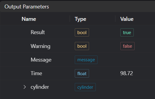
| Result | bool | true/false | true for success false for failure |
| Warning | bool | true/false | true indicates a warning false indicates no warning |
| Message | string | Output success, error, or warning messages. Empty if no error or warning. | |
| Time | float | Operator execution time, unit: ms | |
| cylinder | cylinder | Output cylinder |
Tip
For more detailed explanations of parameter types, please refer to Type Definitions
Exception Troubleshooting
| No. | Exception Information | Corresponding Parameter | Solution |
|---|---|---|---|
| 1 | Input region type is {0}, invalid region type | Region Type | Region input type must be one of: 2D Window/2D Circular Window/2D Polygon Window/Box/Cylindrical Box/Rotated Box/Point Set |
| 2 | Region is empty | 1. Check if selection is empty 2. Check if point set is empty | |
| 3 | Input point cloud is empty | Confirm if IM contains valid points. If no valid points, load point cloud or switch to IM with valid points | |
| 4 | Filter parameters are invalid | Adjust statistical filter parameters | |
| 5 | Point limit is invalid | Set the upper limit of point cloud to be less than the actual point cloud size | |
| 6 | Input point cloud count exceeds limit | Adjust point limit range or replace with point cloud that meets the limit | |
| 7 | Input polygon vertex count is less than 3, cannot form polygon | Add 2D polygon window vertices so that vertex count is at least three |
Example Introduction
Engineering Design
Select the
Load Point Cloudtool to load the required 3D point cloud image to IM0.Select the
3D Cylinder Fittingtool.
Tool Usage
Select the input image for the operation. The image number must match the IM number where the image is located in the project.
Select the region type as Box, move the box to the position to be measured, enclosing the point cloud area to be tested.
Usage Tips
- Use the ROI controller on the image window to drag or scale the box;
- Directly modify the box's start or end point coordinates in the calculation parameters to adjust the box position and size;
Set the parameters.
Check the content you want to display in the result display section.
Click
Testto check if the image window and parameters meet expectations.If there are no issues, click
Save. Run the operator in the run list, and then view the running results in the corresponding IM.