3D Inflection Point Detection
Operator Function
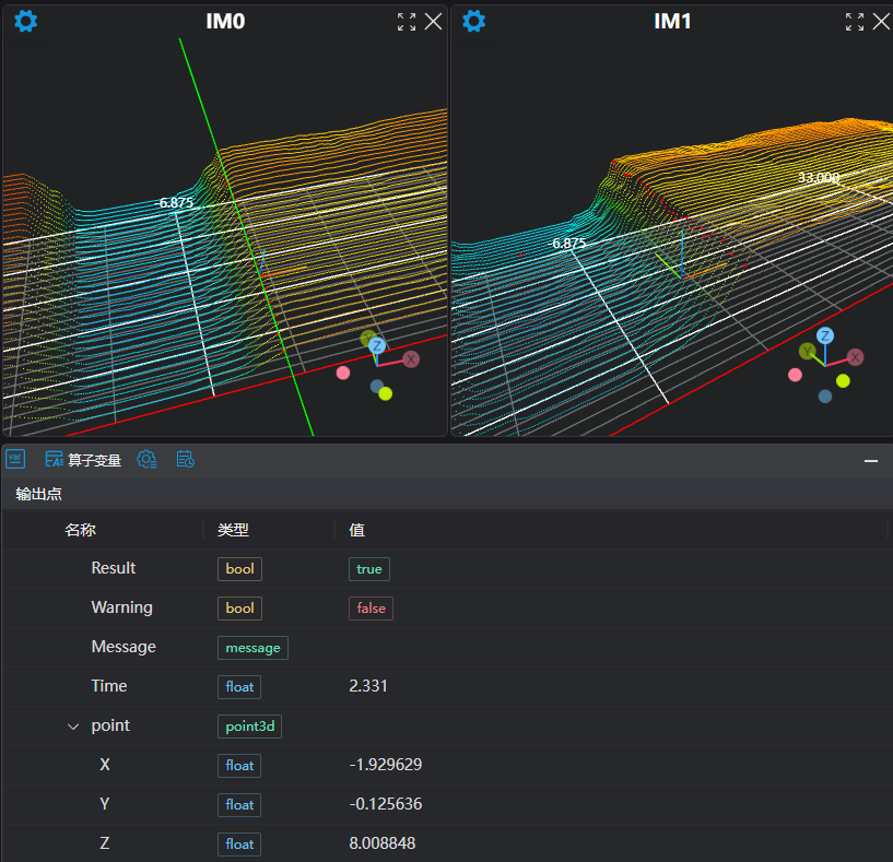
Displays the points with the maximum curvature within the threshold range of the curve in the point cloud area along the X or Y direction, which are called inflection points. Outputs the midpoints of these inflection points or the fitted line.
Parameter Introduction
Input Parameters
| Parameter | Range | Default Value | Description | Illustration |
|---|---|---|---|---|
| Input Image | 0-8 | 0 | IM number of the input image | |
Calculation Parameters
| Parameter | Range | Default Value | Description | Illustration |
|---|---|---|---|---|
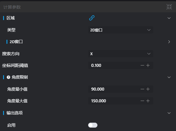
| Region | 2D Window/2D Circular Window/2D Polygon Window/Box/Cylinder Box/Rotated Box/Point Set (Binding Only) | Box | Manually select an appropriate ROI regionExisting ROI regions can be selected via binding | |
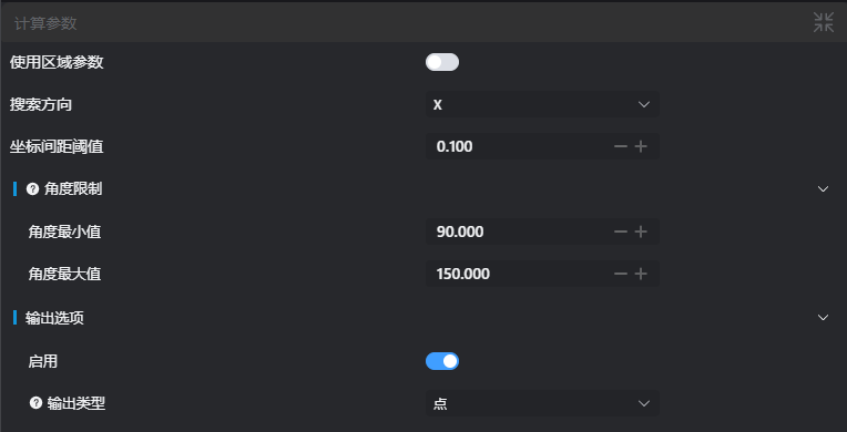
| Search Direction | X/Y | X | X: Search for inflection points along the X direction Y: Search for inflection points along the Y direction | 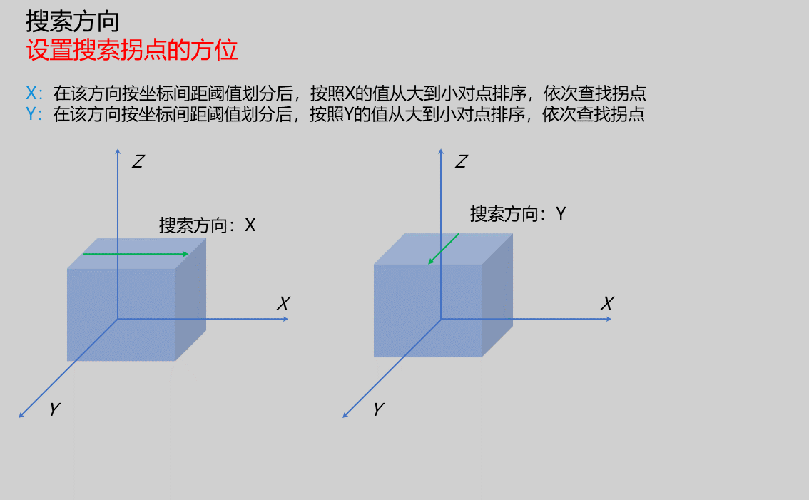 |
| Coordinate Spacing Threshold | 0.100 | If the search direction is X, points with a spacing less than the threshold in the Y direction are considered on the same curve along the X direction; if the search direction is Y, points with a spacing less than the threshold in the X direction are considered on the same curve along the Y direction. | 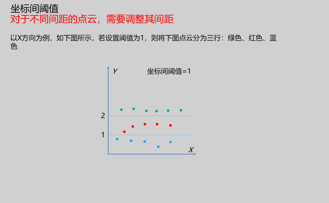 | |
| Angle Limit | Minimum Angle: Set the minimum angle for a point to be recognized as an inflection point Maximum Angle: Set the maximum angle for a point to be recognized as an inflection point | 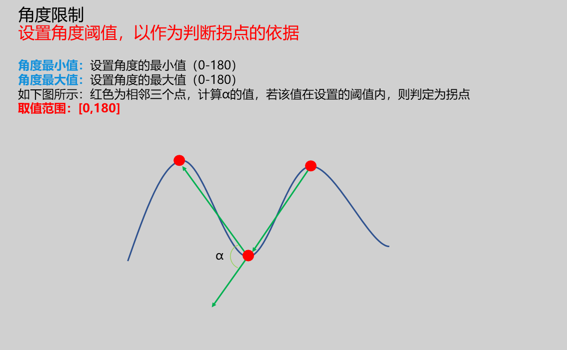 | ||
| Output Option | true/false | false | ||
| Output Type | Point/Line | Point | The Output Type needs to be set when the Output Option is enabled Point: Set the output as a point and push it to the register Line: Set the output as a line and push it to the register | 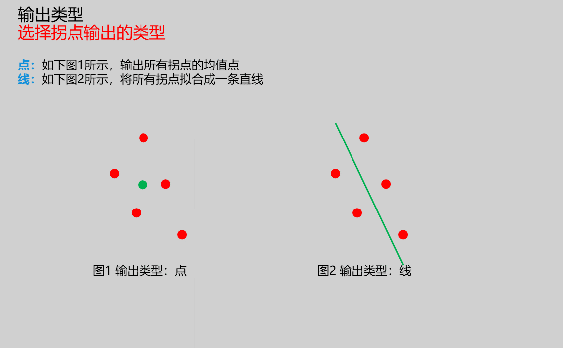 |
Result Display
| Parameter | Range | Default Value | Description | Illustration |
|---|---|---|---|---|
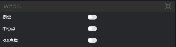
| Inflection Points | true/false | false | Found inflection points; if enabled, they will be displayed in the image | |
| Center Points | true/false | false | Center points of inflection points; if enabled, they will be displayed in the image | |
| Fitted Line | true/false | false | Fitted line of inflection points; if enabled, it will be displayed in the image | |
| ROI Point Set | true/false | false | Only takes effect when the Use Region Parameter is selected. The point set of the ROI-selected region; if enabled, it will be displayed in the image |
Output Parameters
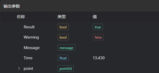
| Name | Type | Range | Description |
|---|---|---|---|
| Result | bool | true/false | true for success, false for failure |
| Warning | bool | true/false | true indicates a warning, false indicates no warning |
| Message | string | Outputs success, error, or warning information; empty if there are no errors or warnings | |
| Time | float | Operator execution time, unit: ms | |
| point | point3d | Coordinate information of the inflection point |
Tip
For detailed explanations of more parameter types, please refer to Type Definition
Troubleshooting
| Serial Number | Error Message | Corresponding Parameter | Solution |
|---|---|---|---|
| 1 | Invalid angle limit parameter | Ensure the minimum angle is less than the maximum angle | |
| 2 | The input region type is {0}, which is an invalid region type | Region Type | Select the region input type from 2D Window/2D Circular Window/2D Polygon Window/Box/Cylinder Box/Rotated Box/Point Set |
| 3 | Empty region | 1. Check if the selection is empty 2. Check if the point set is empty | |
| 4 | Empty input point cloud | Confirm if the IM contains valid points; if not, load the point cloud or switch to an IM with valid points | |
| 5 | Invalid coordinate spacing threshold | Adjust the coordinate spacing threshold appropriately according to the point cloud spacing | |
| 6 | No inflection points found | Appropriately increase the coordinate spacing threshold or angle range | |
| 7 | The output type is {0}, which is an invalid output type | Geometric Type | Select the output type as either Point or Line |
| 8 | The number of vertices of the input polygon is less than 3, making it impossible to form a polygon | Add vertices to the 2D polygon window so that the number of vertices is at least three |
Example Introduction
Project Design
Select the
Load Point Cloudtool to load the 3D point cloud image to be processed into IM0.Select the
3D Inflection Pointtool and set different output types.
Tool Usage
Select the input image to be operated on; the image serial number must be consistent with the IM serial number where the image is located in the project.
Select the region type as Box, move the Box to the position to be measured, and enclose the point cloud to be measured.
Usage Tips
- Drag or scale the Box using the ROI controller on the image window;
- Directly modify the start or end coordinates of the Box in the calculation parameters to adjust the Box position and size;
Set the parameters.
Check the content you want to display in the Result Display column.
Click
Testto check if the image window and parameters meet the expectations.After confirming there are no issues, click
Save, run the operator in the running list, and you can view the running result in the corresponding IM.