3D Angle
Operator Function
Measure the angle between two geometric entities. If a measurement direction is set, it restricts the plane for angle measurement or the rotation axis of the angle.
Parameter Introduction
Input Parameters

| Parameter | Range | Default Value | Description | Illustration |
|---|---|---|---|---|
| Input Image | 0-8 | 0 | The IM number for image input | |
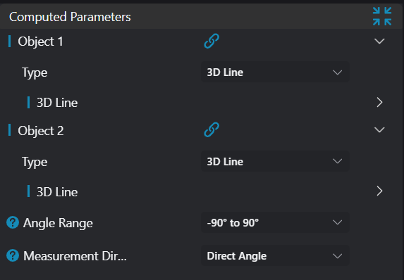
Calculation Parameters
| Parameter | Range | Default Value | Description | Illustration |
|---|---|---|---|---|
| Geometry 1 | This section accepts the first geometric input: See Geometry 1 | |||
| Geometry 2 | This section accepts the second geometric input: See Geometry 2 | |||
| Angle Range | -90° - 90°/0° - 180°/0° - 90° | -90° - 90° | See Angle Range | |
| Measurement Direction | Direct Angle/Project to XY Plane/Project to XZ Plane/Project to YZ Plane | Direct Angle | See Measurement Direction |
Geometry 1
Parameter | Description | Image |
|---|---|---|
| Type | Set manual input type: Line/Plane/Vector | |
| Position | Enabled when input type is 3D Line/Plane; input X, Y, Z coordinates of a point on the line/plane | |
| Direction | Enabled when input type is 3D Line; input direction vector of the line | |
| Vector | Enabled when input type is Vector; input vector parameters | |
| Normal Vector | Enabled when input type is Plane; input normal vector of the plane |
Geometry 2
Parameter | Description | Image |
|---|---|---|
| Type | Set manual input type: Line/Plane/Vector | |
| Position | Enabled when input type is 3D Line/Plane; input X, Y, Z coordinates of a point on the line/plane | |
| Direction | Enabled when input type is 3D Line; input direction vector of the line | |
| Vector | Enabled when input type is Vector; input vector parameters | |
| Normal Vector | Enabled when input type is Plane; input normal vector of the plane |
Angle Range
Parameter | Description | Image |
|---|---|---|
| -90° - 90° | Set output angle between -90° and 90° (this will be the directional difference between two lines) | 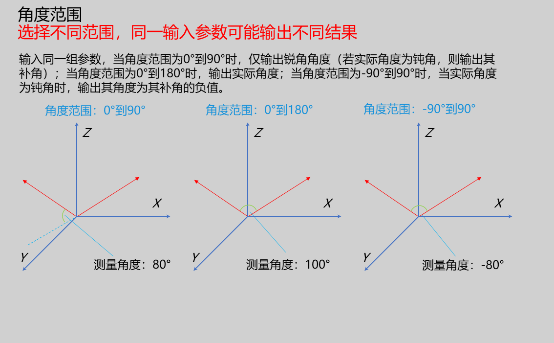 |
| 0° - 180° | Set output angle between 0° and 180° (this will be the opening angle between two lines), taking vector-to-vector angle as an example, as shown below: | |
| 0° - 90° | Set output angle between 0°-90°; ignores rotation axis direction and always gives the possible angle between two lines |
Measurement Direction
Parameter | Description | Image |
|---|---|---|
| Direct Angle | No restriction on measurement direction | 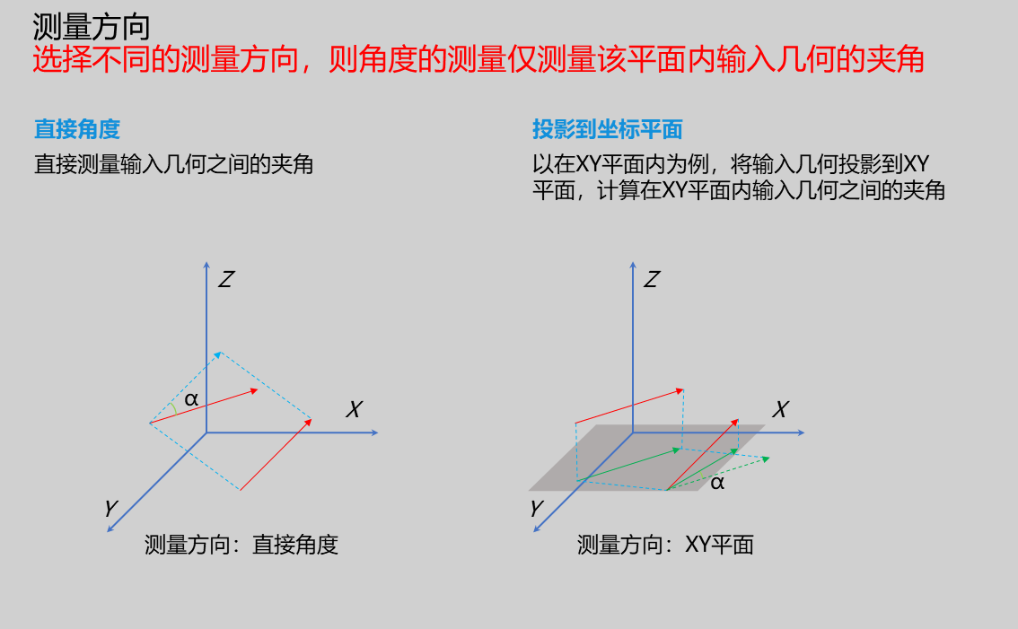 |
| Project to XY Plane | Project lines or vectors onto XY plane for measurement | |
| Project to XZ Plane | Project lines or vectors onto XZ plane for measurement | |
| Project to YZ Plane | Project lines or vectors onto YZ plane for measurement |
Based on different measurement requirements, different measurement objects and directions can be selected:
Vector to Vector Angle: Measure angle between two vectors, with different measurement directions available
| Parameter | Description | Image |
|---|---|---|
| Direct Angle | Directly measures angle between two vectors | 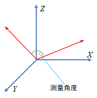 |
| Project to Coordinate Plane | Example in XY plane: only measures angle between vector projections on XY plane | 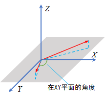 |
Vector to Line Angle: Measure angle between vector and line, with different measurement directions available
| Parameter | Description | Image |
|---|---|---|
| Direct Angle | Directly measures angle between vector and line | 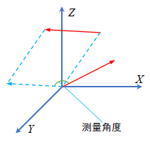 |
| Project to Coordinate Plane | Example in XY plane: only measures angle between vector and line projections on XY plane | 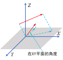 |
Vector to Plane Angle: Measure angle between vector and plane, with different measurement directions available
| Parameter | Description | Image |
|---|---|---|
| Direct Angle | Directly measures angle between vector and plane normal vector; complementary angle gives vector-to-plane angle | 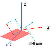 |
| Project to Coordinate Plane | Example in XY plane: measures angle between vector and plane normal vector projections on XY plane; complementary angle gives vector-to-plane angle in XY plane | 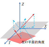 |
Line to Line Angle: Measure angle between two lines, with different measurement directions available
| Parameter | Description | Image |
|---|---|---|
| Direct Angle | Directly measures angle between two lines | 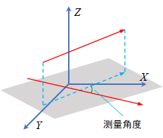 |
| Project to Coordinate Plane | Example in XY plane: only measures angle between line projections on XY plane | 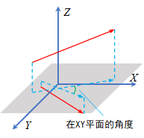 |
Line to Plane Angle: Measure angle between line and plane, with different measurement directions available
| Parameter | Description | Image |
|---|---|---|
| Direct Angle | Directly measures angle between line and plane normal vector; complementary angle gives line-to-plane angle | 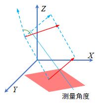 |
| Project to Coordinate Plane | Example in XY plane: measures angle between line and plane normal vector projections on XY plane; complementary angle gives line-to-plane angle in XY plane | 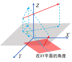 |
Plane to Plane Angle: Measure angle between two planes, with different measurement directions available
| Parameter | Description | Image |
|---|---|---|
| Direct Angle | Directly measures angle between two plane normal vectors | 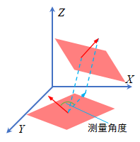 |
| Project to Coordinate Plane | Example in XY plane: only measures angle between plane normal vector projections on XY plane | 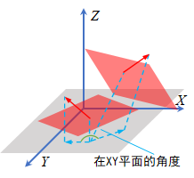 |
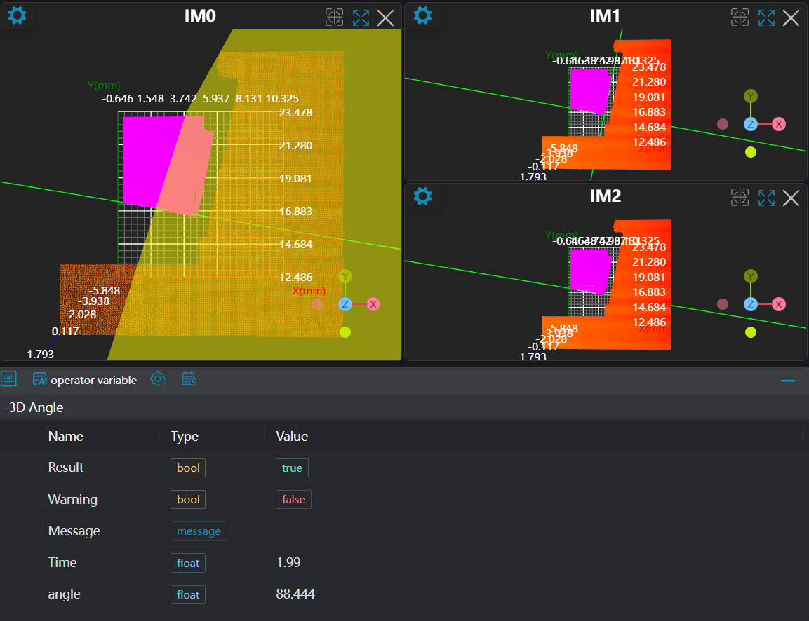
Result Display
| Parameter | Range | Default Value | Description | Illustration |
|---|---|---|---|---|
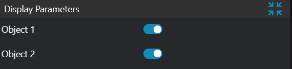
| Geometry 1 | true/false | false | If enabled, display Geometry 1 in the image | |
| Geometry 2 | true/false | false | If enabled, display Geometry 2 in the image |
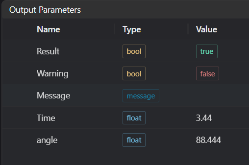
Output Parameters
| Name | Type | Range | Description |
|---|---|---|---|
| Result | bool | true/false | true for success false for failure |
| Warning | bool | true/false | true indicates there is a warning false indicates there is none |
| Message | string | Outputs success, error, or warning information; if there is no error or warning, it is empty | |
| Time | float | Operator execution time, unit: ms | |
| angle | float | Output angle |
Tip
For more detailed explanations of parameter types, please refer to Type Definitions
Exception Troubleshooting
| No. | Exception Information | Corresponding Parameter | Solution |
|---|---|---|---|
| 1 | Input Geometry 1 line parameters invalid | Input line direction vector parameters cannot all be 0 | |
| 2 | Input Geometry 1 plane parameters invalid | Input plane normal vector parameters cannot all be 0 | |
| 3 | Input Geometry 1 type is {0}, invalid geometry type | Geometry Type | Input target 1 type must be one of: 3D Line/Plane/Vector |
| 4 | Input Geometry 2 line parameters invalid | Input line direction vector parameters cannot all be 0 | |
| 5 | Input Geometry 2 plane parameters invalid | Input plane normal vector parameters cannot all be 0 | |
| 6 | Input Geometry 2 type is {0}, invalid geometry type | Geometry Type | Target 2 type must be one of: 3D Line/Plane/Vector |
| 7 | Input Geometry 1 vector parameters invalid | Input vector parameters cannot all be 0 | |
| 8 | Input Geometry 2 vector parameters invalid | Input vector parameters cannot all be 0 |
Example Introduction
Engineering Design
Select the
Load Point Cloudtool to load the 3D point cloud image to be processed into IM0.Select the
3D Croptool to copy IM0 to IM1, IM2 for different operations.Select two
Square Probetools to obtain two lines for measuring line-to-line angle; select oneSquare Probetool to obtain one line and one3D Planetool to obtain a plane for measuring line-to-plane angle.Select the
3D Angletool.
Tool Usage
Select the input image for operation; the image number must match the IM number where the image is located in the project.
Set input geometry
Bind the lines or planes obtained from multiple square probe tools in the previous step as Geometry 1 and Geometry 2.
Set parameters
Check the content you want to display in the result display section
Click
Testto check if the image window and parameters meet expectationsIf there are no issues, click
Save, then run the operator in the run list to view the results in the corresponding IM