3D Contour Step
Operator Function
Measure the step of the contour. When point-to-point mode is selected, measure the step in Z direction from point to reference point (directional, positive when point is above reference point, negative when below). When point-to-line mode is selected, measure the distance from point to reference line (non-directional).
Parameter Introduction
Input Parameters

| Parameter | Range | Default Value | Description | Illustration |
|---|---|---|---|---|
| Input Image | 0-8 | 0 | The IM number for image input | |
Calculation Parameters
| Parameter | Range | Default Value | Description | Illustration |
|---|---|---|---|---|
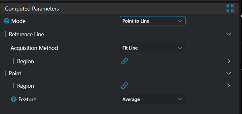
| Mode | See Mode | |||
| Reference Point | See Reference Point | |||
| Reference Line | See Reference Line | |||
| Point | See Point |
Mode
| Parameter | Range | Default Value | Description | Illustration |
|---|---|---|---|---|
| Point to Point | When point-to-point mode is selected, measure the step in Z direction from point to reference point (directional). Positive when point is above reference point, negative when below. | 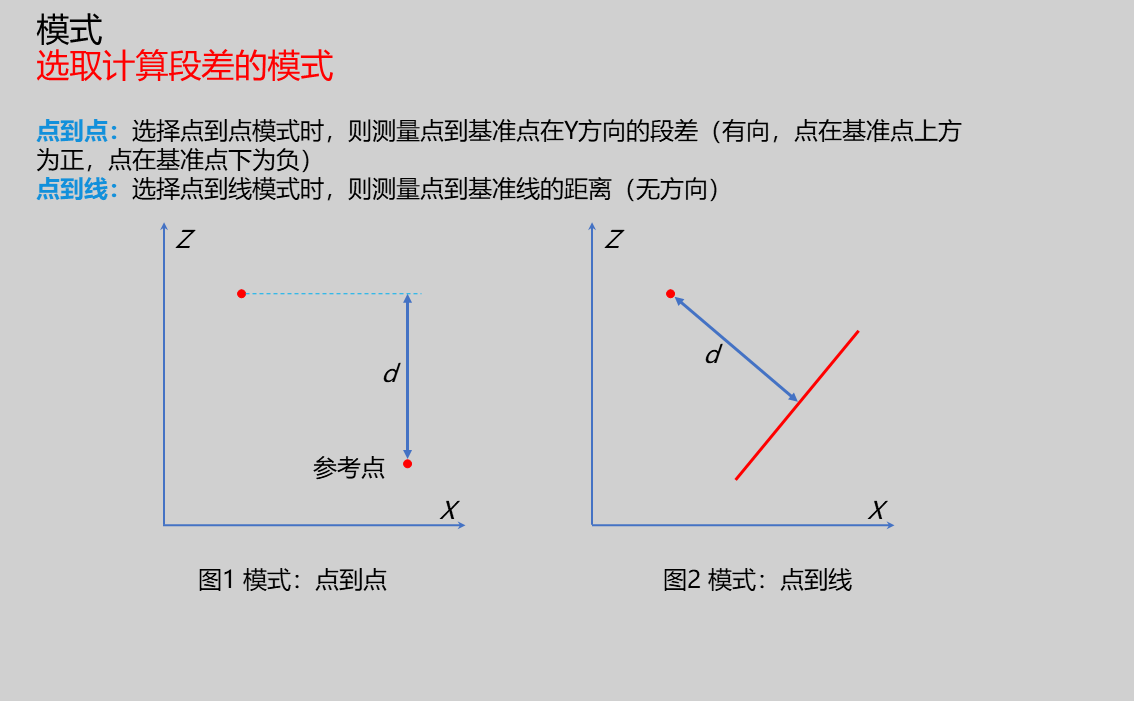 | ||
| Point to Line | When point-to-line mode is selected, measure the distance from point to reference line (non-directional). | |
Reference Point
Only enabled when mode is Point to Point, parameters for selecting input extraction point
| Parameter | Range | Default Value | Description | Illustration |
|---|---|---|---|---|
| Region | Type: Only enabled in manual mode; set manually selected type: 1D Window Start Point: Only enabled in manual mode; input X, Z coordinates of start point End Point: Only enabled in manual mode; input X, Z coordinates of end point | |||
| Point Feature | Min X/Max X/Min Z/Max Z/Mean/Median/Inflection Point/Edge Point | Mean | Min X: Point with smallest X value among all points in region Max X: Point with largest X value among all points in region Min Z: Point with smallest Z value among all points in region Max Z: Point with largest Z value among all points in region Mean: Point formed by calculating X, Z average of all points in region Median: When point count in region is odd, take median point after sorting by X ascending; when even, take average of two median points Inflection Point: Where slope changes significantly on contour Edge Point: Feature points extracted based on adjacent point rise/fall and position after sorting contour left to right | 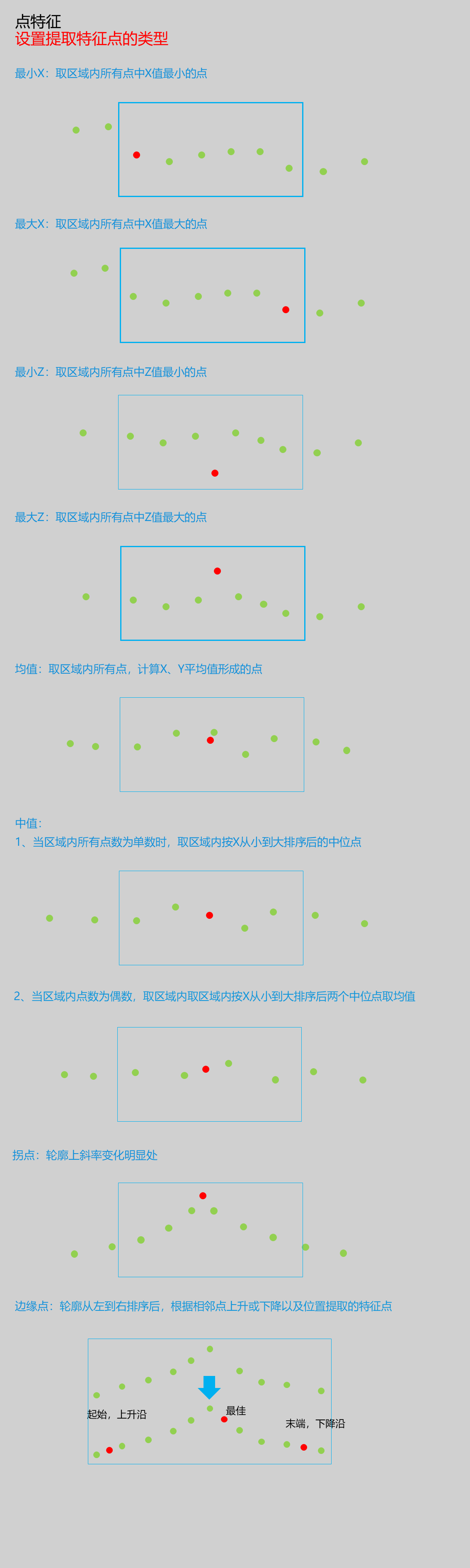 |
| Inflection Point Search Type | -X/+X/-Z/+Z | +Z | -X: Search for leftmost inflection point +X: Search for rightmost inflection point -Z: Search for bottommost inflection point +Z: Search for topmost inflection point | |
| Noise Removal | 0.000 | Enable: If enabled, filter out inflection points with small jumps Threshold: Minimum difference to filter out interference points in Z direction | ||
| Edge Point Direction | Rising Edge/Falling Edge/Rising or Falling Edge | Rising or Falling Edge | Rising Edge: Search in rising direction from left to right along contour Falling Edge: Search in falling direction from left to right along contour Rising or Falling Edge: Search in rising or falling direction from left to right | |
| Edge Point Position | First/Last/Best | Best | First: First edge point meeting requirements from left to right on contour Last: Last edge point meeting requirements from left to right on contour Best: Edge point with largest height difference among those meeting requirements from left to right |
Reference Line
Only enabled when mode is Point to Line, parameters for selecting input extraction point
| Parameter | Range | Default Value | Description | Illustration |
|---|---|---|---|---|
| Acquisition Method | Horizontal Reference Line/Fitted Line | Fitted Line | Select method to obtain reference line Horizontal Reference Line: Set a Z value as horizontal reference line Fitted Line: Use points in region to fit line as reference line |  |
| Value | 0.000 | Only enabled when acquisition method is Horizontal Reference Line; set value for horizontal reference line | ||
| Region | Only enabled when acquisition method is Fitted Line; fit line based on points in region Type: Only enabled in manual mode; set manually selected type: 1D Window Start Point: Only enabled in manual mode; input X, Z coordinates of start point End Point: Only enabled in manual mode; input X, Z coordinates of end point |
Point
Parameters for selecting input extraction point
| Parameter | Range | Default Value | Description | Illustration |
|---|---|---|---|---|
| Region | 1D Window | 1D Window | Type: Only enabled in manual mode; set manually selected type as 1D Window Start Point: Only enabled in manual mode; input X, Z coordinates of start point End Point: Only enabled in manual mode; input X, Z coordinates of end point | |
| Point Feature | Min X, Max X, Min Z, Max Z, Mean, Median, Inflection Point, Edge Point | Mean | Min X: Point with smallest X value among all points in region Max X: Point with largest X value among all points in region Min Z: Point with smallest Z value among all points in region Max Z: Point with largest Z value among all points in region Mean: Point formed by calculating X, Z average of all points in region Median: When point count in region is odd, take median point after sorting by X ascending; when even, take average of two median points Inflection Point: Where slope changes significantly on contour Edge Point: Feature points extracted based on adjacent point rise/fall and position after sorting contour left to right | |
| Inflection Point Search Type | -X/+X/-Z/+Z | +Z | -X: Search for leftmost inflection point +X: Search for rightmost inflection point -Z: Search for bottommost inflection point +Z: Search for topmost inflection point | |
| Noise Removal | 0.000 | Only enabled when feature point is Inflection Point Enable: If enabled, filter out inflection points with small jumps Threshold: Minimum difference to filter out interference points in Z direction | ||
| Edge Point Direction | Rising Edge/Falling Edge/Rising or Falling Edge | Rising or Falling Edge | Only enabled when feature point is Edge Point Rising Edge: Search in rising direction from left to right along contour Falling Edge: Search in falling direction from left to right along contour Rising or Falling Edge: Search in rising or falling direction from left to right | |
| Edge Point Position | First/Last/Best | Best | Only enabled when feature point is Edge Point First: First edge point meeting requirements from left to right on contour Last: Last edge point meeting requirements from left to right on contour Best: Edge point with largest height difference among those meeting requirements from left to right |
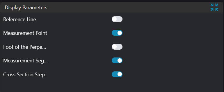
Result Display
| Parameter | Range | Default Value | Description | Illustration |
|---|---|---|---|---|
| Reference Line | true/false | false | Reference line for step calculation; if enabled, displayed in the image | |
| Reference Point | true/false | false | Reference point for step calculation; if enabled, displayed in the image | |
| Foot of Perpendicular | true/false | false | Foot of perpendicular from point to line; if enabled, displayed in the image | |
| Measurement Point | true/false | false | Searched measurement point; if enabled, displayed in the image | |
| Measurement Segment | true/false | false | Step measurement segment; if enabled, displayed in the image | |
| Step Value | true/false | false | Step value; if enabled, displayed in the image |
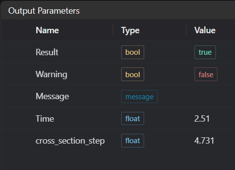
Output Parameters
| Name | Type | Range | Description |
|---|---|---|---|
| Result | bool | true/false | true for success false for failure |
| Warning | bool | true/false | true indicates there is a warning false indicates there is none |
| Message | string | Outputs success, error, or warning information; if there is no error or warning, it is empty | |
| Time | float | Operator execution time, unit: ms | |
| cross_section_step | float | Output step value |
Tip
For more detailed explanations of parameter types, please refer to Type Definitions
Exception Troubleshooting
| No. | Exception Information | Corresponding Parameter | Solution |
|---|---|---|---|
| 1 | Failed to get feature points in crop region | Adjust start and end parameters of point acquisition region to ensure valid points exist in selected area | |
| 2 | Input region type is {0}, invalid region type | Region Type | Input region type must be 1D Window |
| 3 | Invalid region for input point | Adjust region parameters so input point cloud in region is not empty | |
| 4 | No inflection point found | Adjust inflection point parameters | |
| 5 | No edge point found | Adjust edge point parameters | |
| 6 | Input feature point type is {0}, invalid feature point type | Feature Point Type | Select one of: Min X/Max X/Min Z/Max Z/Mean Point/Median Point/Inflection Point/Edge Point |
| 7 | Invalid region for input line | Input line direction vector parameters cannot all be 0 | |
| 8 | Input reference line acquisition method is {0}, invalid acquisition method | Acquisition Method | Select reference line acquisition method as Fitted Line/Horizontal Reference Line |
| 9 | Input mode is {0}, invalid input mode | Select mode as Point to Point/Point to Line | |
| 10 | Input point cloud is empty | Confirm if IM contains valid points; if no valid points, load point cloud or switch to IM with valid points |
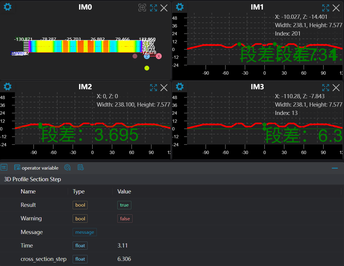
Example Introduction
Engineering Design
Select the
Load Point Cloudtool to load the 3D point cloud image to be processed into IM0.Select the
3D Contour Extractiontool to extract contours into IM1, IM2, IM3 respectively.Select the
3D Contour Steptool to measure point-to-point and point-to-line contour steps respectively.
Tool Usage
Select the input image for operation; the image number must match the IM number where the image is located in the project.
Set input point or line:
If it's a point or fitted line, set the window position to get points or lines; if it's a baseline, set the baseline value.
Set parameters
Check the content you want to display in the result display section
Click
Testto check if the image window and parameters meet expectationsIf there are no issues, click
Save, then run the operator in the run list to view the results in the corresponding IM