3D Contour Area
Operator Function
As shown in the figure below, this operator calculates the area of a closed contour or the area enclosed by contour points and a reference line
Parameter Introduction
Input Parameters

| Parameter | Range | Default Value | Description | Illustration |
|---|---|---|---|---|
| Input Image | 0-8 | 0 | The IM number for image input | |
Calculation Parameters
| Parameter | Range | Default Value | Description | Illustration |
|---|---|---|---|---|
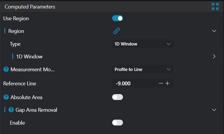
| Region | 1D Window | 1D Window | Type: Only enabled in manual mode; set manually selected type: 1D Window Start Point: Only enabled in manual mode; input X, Z coordinates of start point End Point: Only enabled in manual mode; input X, Z coordinates of end point | |
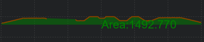
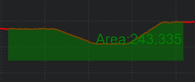
| Measurement Mode | Closed Contour/Contour to Line | Contour to Line | Closed Contour: If this mode is selected, directly output the polygon area enclosed by the contour. For more accurate results, input contour should preferably be a single contour Contour to Line: If this mode is selected, output the area from contour to reference line | 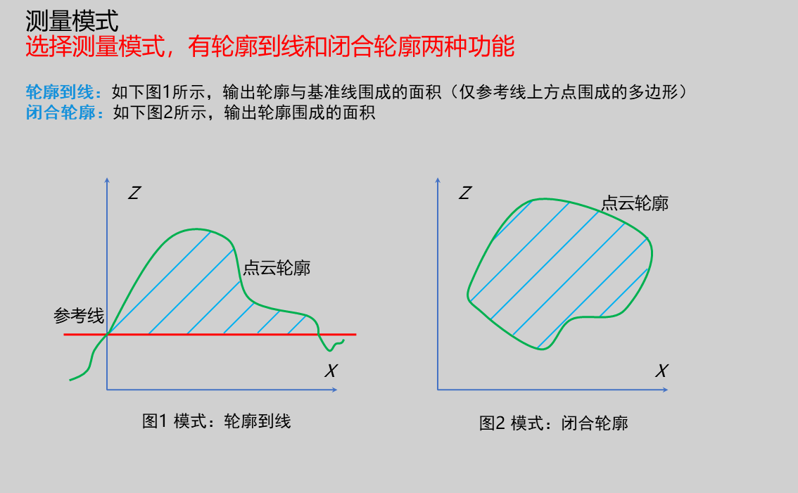 |
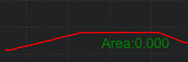
| Reference Line | 0.000 | Only enabled when measurement mode is Contour to Line; input reference height (z) valuePoint cloud below reference line: Area enclosed by reference line and point cloud is positive areaPoint cloud above reference line: Area enclosed by reference line and point cloud is 0 | 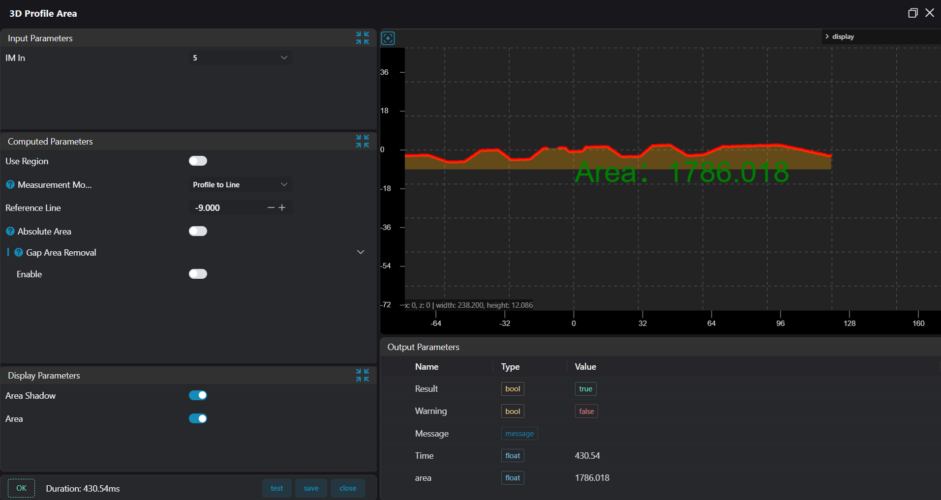 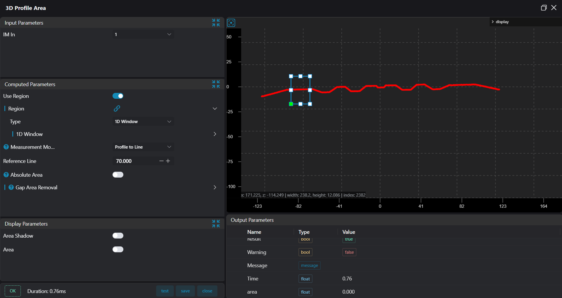 | |
| Absolute Area | true/false | false | Only enabled when measurement mode is Contour to Line; if enabled, calculate area enclosed by contour below reference height as positiveWhen absolute area is enabled, all enclosed areas are calculated as positive area as shown below: | 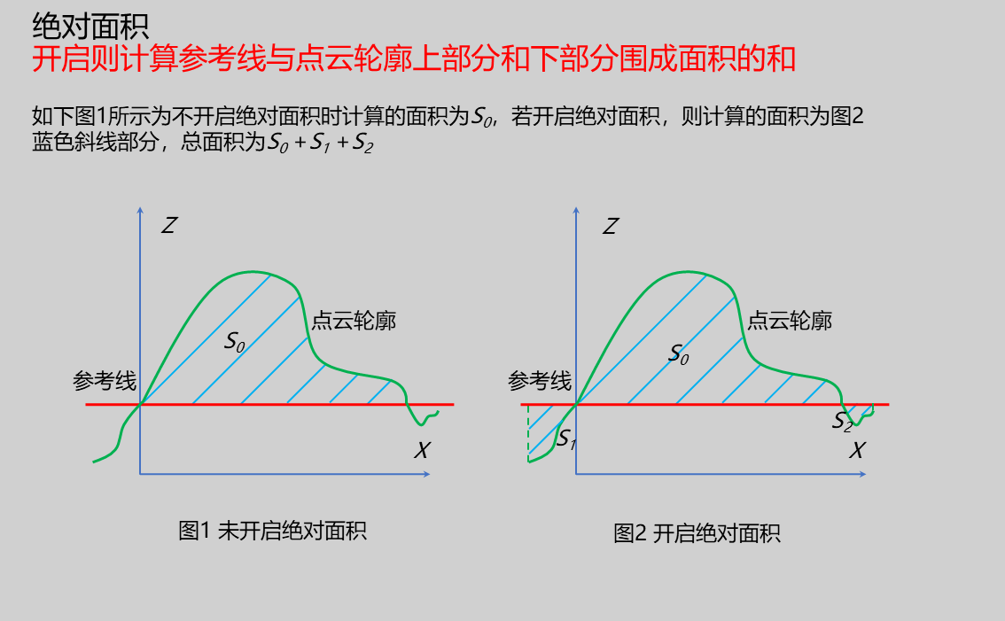 |
| Gap Area Removal | true/false | false | Only enabled when measurement mode is Contour to Line; if enabled, contour points considered as gaps will be removed based on maximum spacing | |
| Gap Width Threshold | 0.010 | Required when Gap Area Removal is enabledSet points beyond this spacing as gaps; these points will not be used as contour points for area calculation Gap Area Removal Enabled: When gap area removal is enabled, gap area is not calculated Gap Area Removal Disabled: When gap area removal is not enabled, area including gaps is calculated | 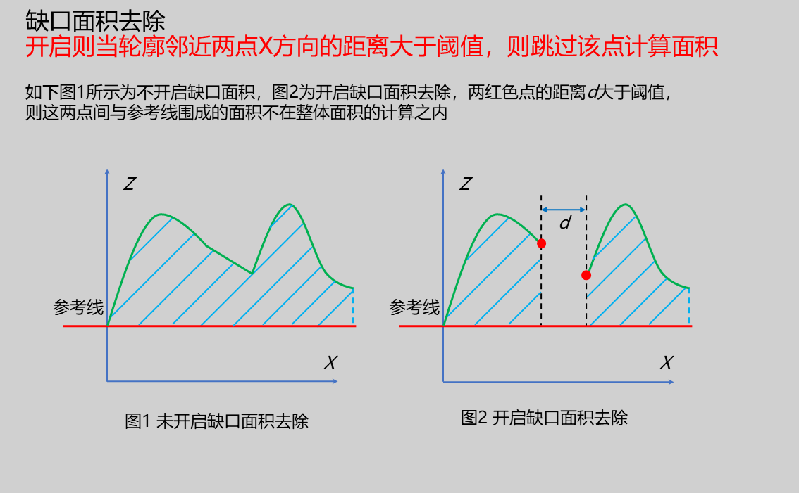 |
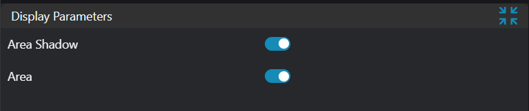
Result Display
| Parameter | Range | Default Value | Description | Illustration |
|---|---|---|---|---|
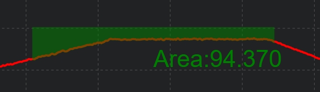
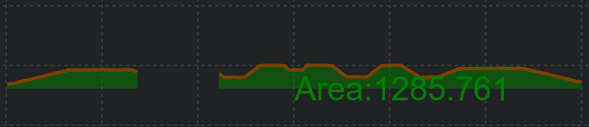
| Area Shading | true/false | false | If enabled, display area shading in the image | |
| Area | true/false | false | Area value; if enabled, displayed in the image |
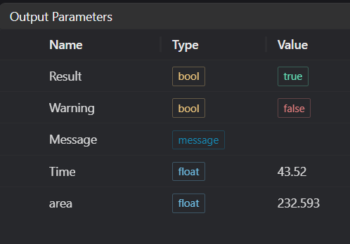
Output Parameters
| Name | Type | Range | Description |
|---|---|---|---|
| Result | bool | true/false | true for success false for failure |
| Warning | bool | true/false | true indicates there is a warning false indicates there is none |
| Message | string | Outputs success, error, or warning information; if there is no error or warning, it is empty | |
| Time | float | Operator execution time, unit: ms | |
| area | float | Output area |
Tip
For more detailed explanations of parameter types, please refer to Type Definitions
Exception Troubleshooting
| No. | Exception Information | Corresponding Parameter | Solution |
|---|---|---|---|
| 1 | Region crop failed | None | Check if selection is empty |
| 2 | Input region type is {0}, invalid region type | Region Type | Region input type must be 1D Window |
| 3 | Point cloud input invalid | None | Adjust start and end parameters of point acquisition region to ensure valid points exist in selected area |
| 4 | Input gap width threshold invalid | None | Appropriately reduce this parameter |
| 5 | Input mode is {0}, invalid input mode | Mode | Select mode as Closed Contour/Contour to Line |
Example Introduction
Engineering Design
Select the
Load Point Cloudtool to load the 3D point cloud image to be processed into IM0;Select the
3D Regiontool to select the region where plane fitting is needed;Select the
3D Planetool, using the output of the3D Regiontool as input, fit a plane and transform the point cloud;Select the
3D Contour Extractiontool to extract required contour into IM1;Select the
3D Contour Areatool
Tool Usage
Select the input image for operation; the image number must match the IM number where the image is located in the project.
Either do not enable Use Region Parameters, or enable region and select region type as 1D Window, move the 1D Window to the position to be measured, enclosing the point cloud to be measured.
Set parameters
Check the content you want to display in the result display section
Click
Testto check if the image window and parameters meet expectationsIf there are no issues, click
Save, then run the operator in the run list to view the results in the corresponding IM
Absolute Area Enabled
Absolute Area Disabled
Gap Area Removal Enabled
Gap Area Removal Disabled