Pin Matching
Operator Function
This operator is used to compare the X, Y coordinates and height information of pins using a recipe, and output the pins' X, Y coordinates, height and spacing information, as well as the comparison results with the recipe. Note: The standard part point cloud used must be preprocessed.
Parameter Introduction
Input Parameters

| Parameter | Range | Default Value | Description | Illustration |
|---|---|---|---|---|
| Input Image | 0-8 | 0 | The IM number for image input | |
Calculation Parameters
| Parameter | Range | Default Value | Description | Illustration |
|---|---|---|---|---|
| Use Region Parameters | true/false | false | If enabled, use Region as input; if not enabled, use Input Image as input | |
| Region | 2D Window/2D Circular Window/2D Polygon Window/Box/Cylinder Box/Rotated Box/Point Set (binding only) | Box | Manually select an appropriate ROI regionCan bind to select existing ROI regions | |
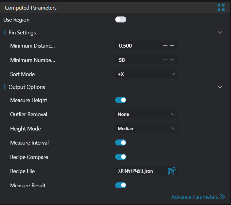
| Pin Minimum Spacing | 0.5 | Minimum distance between two pins | ||
| Pin Minimum Points | 50 | Minimum number of points for a pin | ||
| Sorting Method | +X/-X/+Y/-Y | +X | +X: Pins sorted from left to right, top to bottom -X: Pins sorted from right to left, bottom to top+Y: Pins sorted from right to left, bottom to top -Y: Pins sorted from right to left, bottom to top | 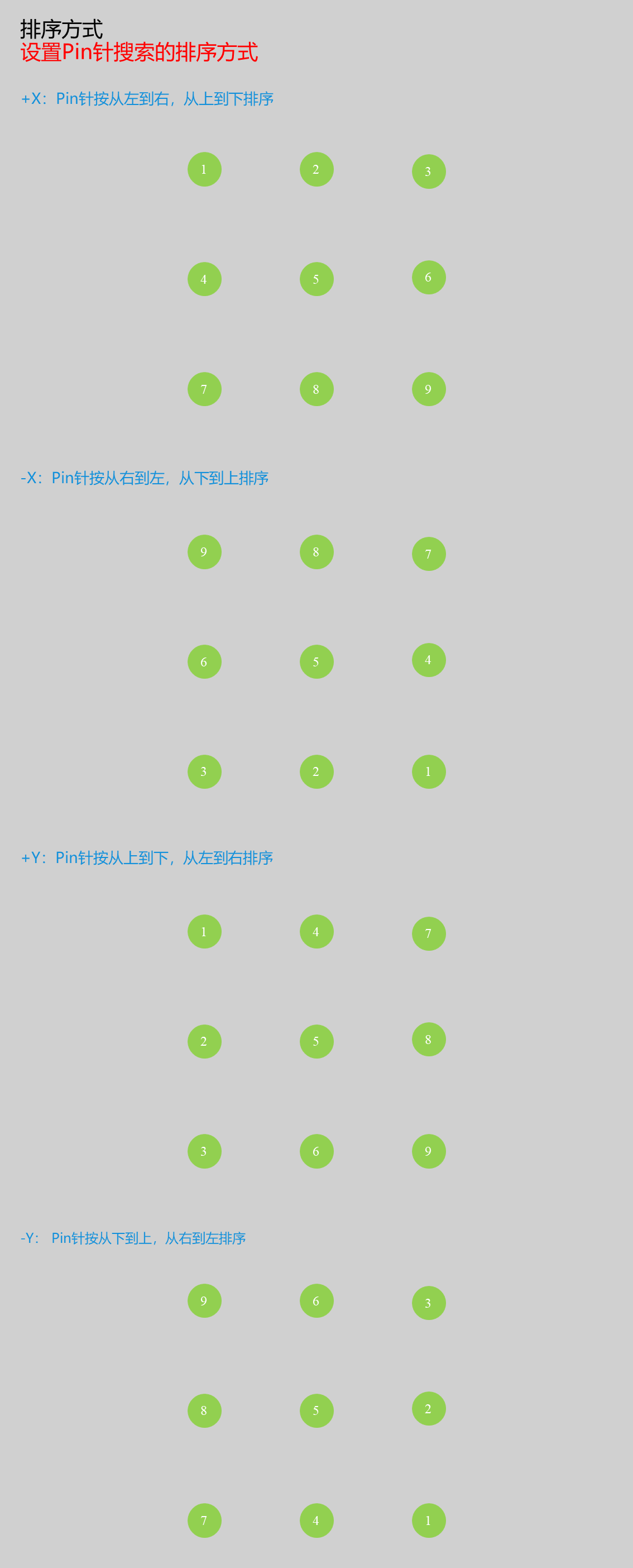 |
| Pin Height | true/false | false | If enabled, output pin height information | |
| Outlier Removal | Percentile Filter/None | Only enabled when pin height measurement is enabled; select filtering method | ||
| Low Removal Percentage | 0.000-50.000 | 10.000 | Remove noise points in the low Z direction according to this ratio. For example, when the ratio is set to 10%, remove the lowest 10% of points | 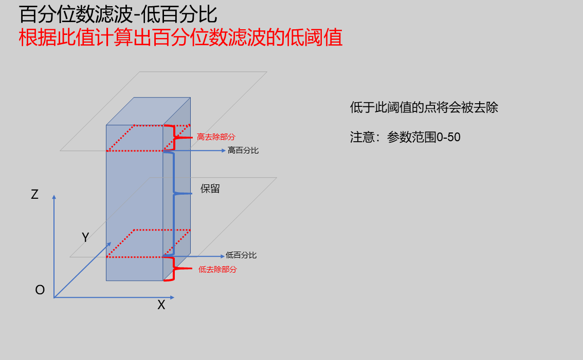 |
| High Removal Percentage | 0.000-50.000 | 10.000 | Remove noise points in the high Z direction according to this ratio. For example, when the ratio is set to 10%, remove the highest 10% of points |  |
| Height Mode | Minimum, Maximum, Mean, Median, Standard Deviation, Percentile | Median | Provide 6 methods for calculating height | |
| Percentage | 10 | Enabled when mode is Percentile; input percentile, e.g., input 50 to take the middle 50% of points for height calculation | ||
| Pin Spacing | true/false | false | If enabled, output pin spacing information | |
| Recipe Comparison | true/false | false | If enabled, output comparison information with the pin recipe | |
| Recipe Path | true/false | false | Enabled when recipe comparison is enabled; input the path of the pin recipe (only supports .json recipe files with array named "recipe") | |
| Measurement Result | true/false | false | Can be enabled when recipe comparison is enabled; when enabled, output the comparison result with the pin recipe, displayed on the interface and saved in global variables | |
| Pin Offset | 1.000 | Set the offset in X or Y direction for pin sorting; if within the offset range, considered in the same row/column | 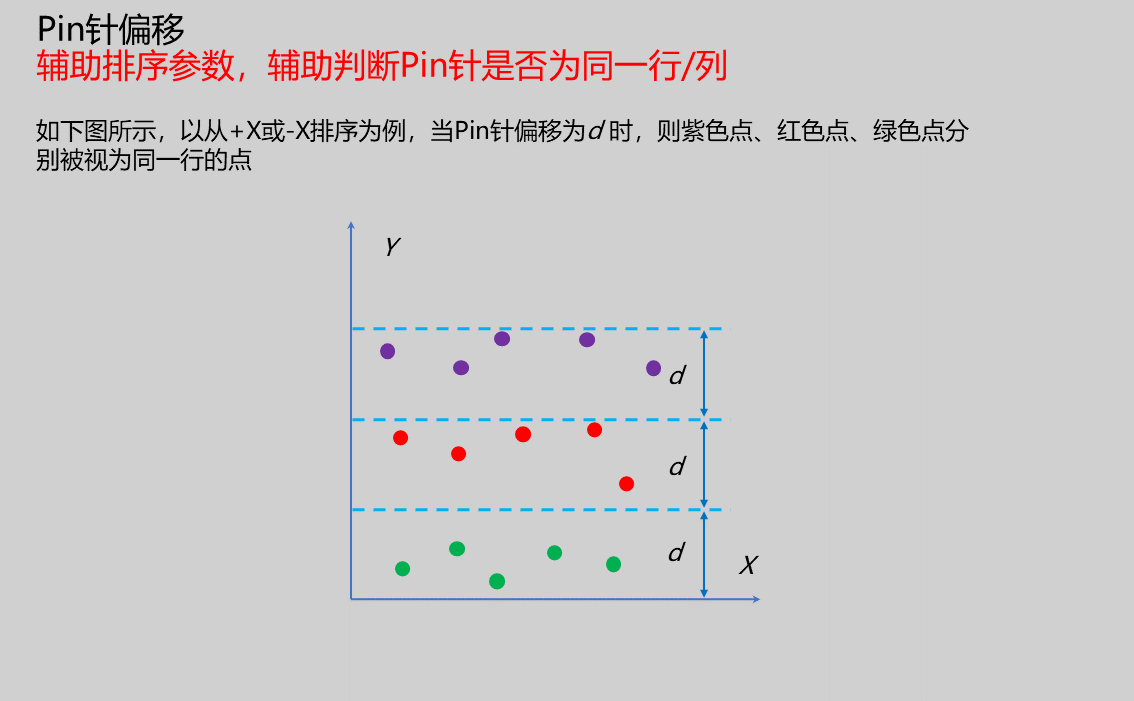 |
Result Display
| Parameter | Range | Default Value | Description | Illustration |
|---|---|---|---|---|
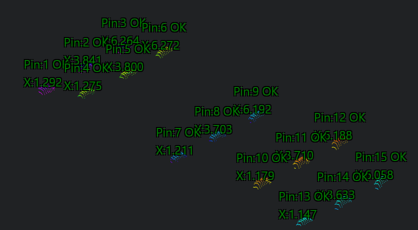
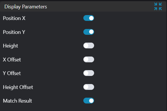
| Sequence Number | true/false | false | Pin sequence number; if enabled, displayed in the image | |
| X Coordinate | true/false | false | Pin X coordinate; if enabled, displayed in the image | |
| Y Coordinate | true/false | false | Pin Y coordinate; if enabled, displayed in the image | |
| Height | true/false | false | Pin height; if enabled, displayed in the image | |
| X Offset Value | true/false | false | Pin X offset value; if enabled, displayed in the image | |
| Y Offset Value | true/false | false | Pin Y offset value; if enabled, displayed in the image | |
| Height Offset Value | true/false | false | Pin height offset value; if enabled, displayed in the image | |
| Matching Result | true/false | false | Pin matching result; if enabled, display pin sequence number and OK or NG in the image | |
| ROI Point Set | true/false | false | Only effective when Use Region Parameters is selected; the point set of the ROI selected region; if enabled, displayed in the image |
Output Parameters
| Name | Type | Range | Description |
|---|---|---|---|
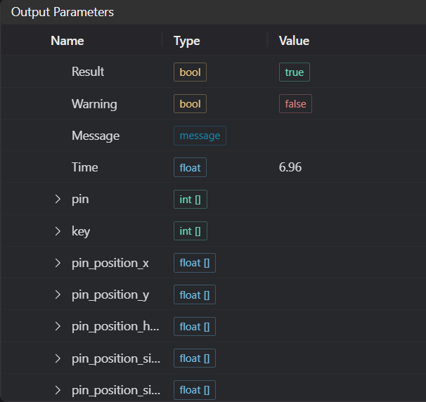
| Result | bool | true/false | true for success false for failure |
| Warning | bool | true/false | true indicates there is a warning false indicates there is none |
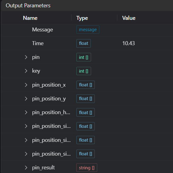
| Message | string | Outputs success, error, or warning information; if there is no error or warning, it is empty | |
| Time | float | Operator execution time, unit: ms | |
| pin | int[] | Output pin sequence numbers | |
| key | int[] | Output pin key positions | |
| pin_position_x | float[] | Output pin X coordinates | |
| pin_position_y | float[] | Output pin Y coordinates | |
| pin_position_height | float[] | Output pin height values | |
| pin_position_side_x | float[] | Output pin spacing in X direction | |
| pin_position_side_y | float[] | Output pin spacing in Y direction | |
| pin_position_side_height | float[] | Output pin height spacing | |
| pin_result | string[] | Output pin matching results |
Tip
For more detailed explanations of parameter types, please refer to Type Definitions
Exception Troubleshooting
| No. | Exception Information | Corresponding Parameter | Solution |
|---|---|---|---|
| 1 | Input region type is {0}, invalid region type | Region Type | Region input type must be one of: 2D Window/2D Circular Window/2D Polygon Window/Box/Cylinder Box/Rotated Box/Point Set |
| 2 | Region is empty | 1. Check if selection is empty 2. Check if point set is empty | |
| 3 | Input point cloud is empty | Confirm if IM contains valid points; if no valid points, load point cloud or switch to IM with valid points | |
| 4 | Pin extraction failed | Modify pin setting parameters | |
| 5 | Input sorting method is {0}, invalid sorting method | Sorting Method | Select sorting method as one of +X/-X/+Y/-Y |
| 6 | Input height mode is {0}, invalid sorting method | Height Mode | Select mode as Maximum/Minimum/Median/Mean/Removal Percentage |
| 7 | File "{0}" does not exist or cannot be accessed | File Path | Input valid recipe path |
| 8 | File "{0}" failed to load | File Path | Input valid path and must be a json file |
| 9 | File does not contain "recipe" | Use a json file with the "recipe" key | |
| 10 | Recipe count does not match the number of detected pins | The recipe array must match the number of detected pins | |
| 11 | The {0}th pin does not have the {1} field | Sequence number, recipe variable name | Use the i-th set of recipe files with recipe variable parameters |
| 12 | Input polygon vertex count is less than 3, cannot form a polygon | Add 2D polygon window vertices so that the vertex count is at least three |
Example Introduction
Engineering Design
Select the
Load Point Cloudtool to load the 3D point cloud image to be processed into IM0;Select the
3D Regiontool to select the region for plane fitting;Select the
3D Planetool, using the output of the3D Regiontool as input, fit a plane and transform the point cloud;Select the
3D Square Probetool to search for positioning points;Select the
3D Position Adjustmenttool, using the positioning point as the new origin, adjust the point cloud position;Select the
3D Croptool to crop the pin point cloud;Select the
3D Transformationtool to adjust the pin point cloud to a suitable position;Select the
Pin Recipe Creationtool to obtain the pin recipe file;Select the
Pin Matchingtool to detect pins.
Tool Usage
Select the input image for operation; the image number must match the IM number where the image is located in the project.
Either do not enable Use Region Parameters, or enable region and select region type as Box, move the box to the position to be measured, enclosing the point cloud to be measured.
Set parameters.
Check the content you want to display in the result display section.
Click
Testto check if the image window and parameters meet expectations.If there are no issues, click
Save, then run the operator in the run list to view the results in the corresponding IM.