Create ROI Array
Operator Function
Create m×n ROIs according to requirements
Parameter Introduction
Input Parameters

| Parameter | Range | Default Value | Description | Illustration |
|---|---|---|---|---|
| Input Image | 0-8 | 0 | The IM number for image input | |
Calculation Parameters
| Parameter | Range | Default Value | Description | Illustration |
|---|---|---|---|---|
| Region | 2D Window/2D Circular Window/Box/Cylinder Box | Box | Manually select an appropriate ROI regionCan bind to select existing ROI regions | |
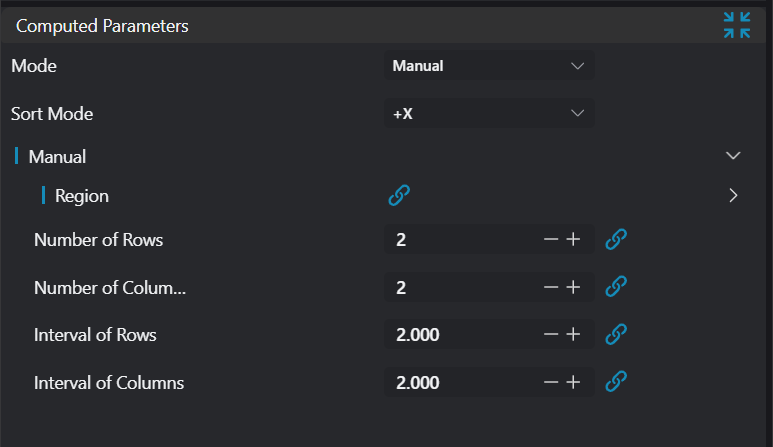
| Mode | Manual/Automatic | Manual | Manual mode generates multiple ROI arrays in the input ROI style; Automatic mode automatically divides the input ROI into an ROI array | |
| Manual | Generate ROI array manually | |||
| Automatic | Generate ROI array automatically | |||
| Boundary | 2D Window/Box | Box | Set the boundary type in automatic mode. When the boundary is a 2D Window, the region only supports 2D Window/2D Circular Window; when the boundary is a Box, all region types are supported | |
| ROI Type | 2D Window/2D Circular Window/Box/Cylinder Box | Box | Set the output ROI type | |
| ROI Bounding Rectangle Length | 5.0 | The length of the bounding rectangle for the generated ROI array | ||
| ROI Bounding Rectangle Width | 5.0 | The width of the bounding rectangle for the generated ROI array | ||
| Row Spacing | 2.0 | The row spacing value for the generated ROI array | ||
| Column Spacing | 2.0 | The column spacing value for the generated ROI array | ||
| Number of Rows | 2 | The number of rows for the generated ROI array | ||
| Number of Columns | 2 | The number of columns for the generated ROI array |
Result Display
| Parameter | Range | Default Value | Description | Illustration |
|---|---|---|---|---|
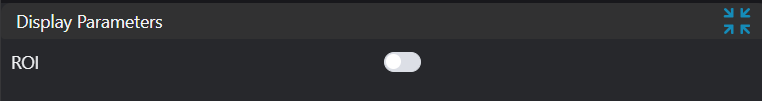
| ROI | true/false | false | If enabled, display the created ROIs in the image |
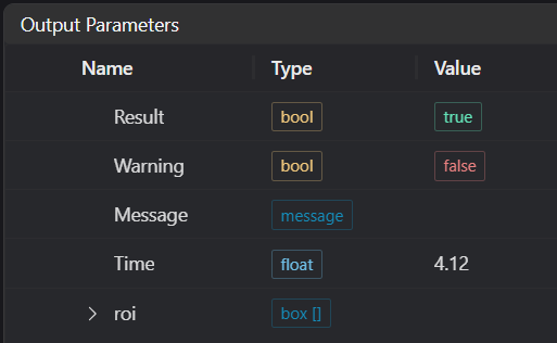
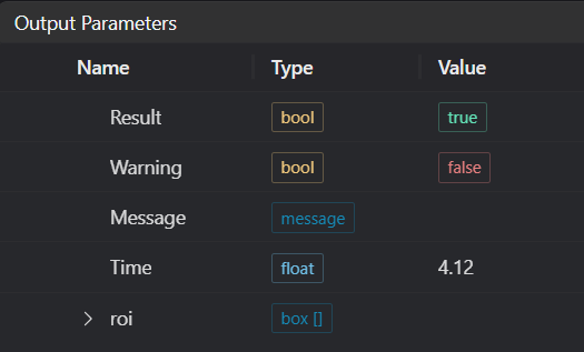
Output Parameters
| Name | Type | Range | Description |
|---|---|---|---|
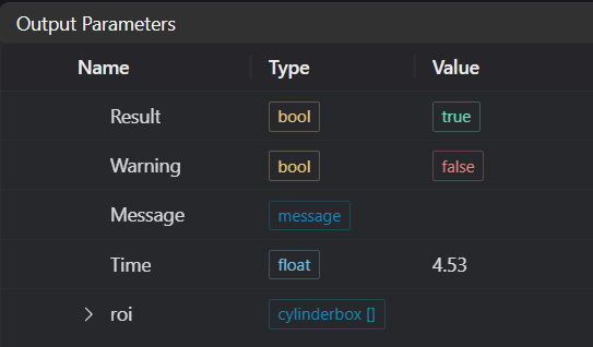
| Result | bool | true/false | true for success false for failure |
| Warning | bool | true/false | true indicates a warning false indicates none |
| Message | string | Output success, error, or warning messages. Empty if no error or warning | |
| Time | float | Operator execution time, unit: ms | |
| roi | window2d[]/circlewindow2d[]/box[]/cylinderbox[] | Output ROIs |
Tip
For more detailed explanations of parameter types, please refer to Type Definitions
Exception Troubleshooting
| No. | Exception Information | Corresponding Parameter | Solution |
|---|---|---|---|
| 1 | The input mode is {0}, invalid mode | Mode | Select either manual or automatic mode |
| 2 | The input boundary type in automatic mode is {0}, invalid boundary type | Boundary Type | Select boundary type as 2D Window/Box |
| 3 | Invalid 2D Window parameters input | The difference in any x or y between the input start and end points is not 0 | |
| 4 | Invalid Box parameters input | The difference in any x, y, z between the input start and end points is not 0 | |
| 5 | In automatic mode with boundary type as 2D Window, the input region type is invalid | Region Type | Select region type as 2D Window/2D Circular Window |
| 6 | In automatic mode with boundary type as Box, the input region type is invalid | Region Type | Select region type as 2D Window/2D Circular Window/Box/Cylinder |
| 7 | The input region type in manual mode is {0}, invalid region type | Region Type | Select region type as 2D Window/2D Circular Window/Box/Cylinder |
| 8 | Spacing calculation is negative, cannot create ROI array | Increase the boundary dimensions or decrease the number of rows/columns | |
| 9 | ROI count exceeds the upper limit of 10000, cannot create ROI array | Modify relevant parameters to reduce the number of ROIs created | |
| 10 | The input automatic mode is {0}, invalid automatic mode | Mode | Select automatic mode as either based on rows/columns or based on spacing |
| 11 | ROI exceeds the set boundary, cannot create ROI array | Increase the boundary dimensions or decrease the spacing |
Example Introduction
Engineering Design
Select the
Load Point Cloudtool to load the required 3D point cloud image into IM0;Select the
Create ROI Arraytool.
Tool Usage
Select the input image for operation. The image number must match the IM number where the image is located in the project.
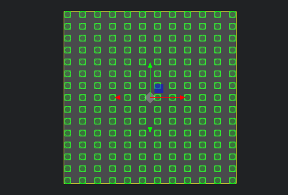
Do not enable the Use Region parameter, or enable Region and select the region type as Box, then move the box to the target position.
Usage Tips
- Use the ROI controller on the image window to drag or scale the box;
- Directly modify the start or end coordinates of the box in the calculation parameters to adjust the box position and size.
Set the parameters.
Check the desired display content in the Result Display section.
Click
Testto check if the image window and parameters meet expectations.If everything is correct, click
Save, then run the operator in the run list. You can view the results in the corresponding IM.
Manual Creation
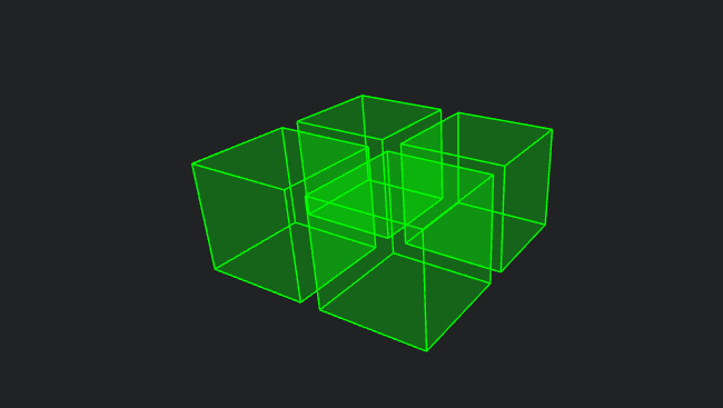
Automatic Creation