Point Cloud to Depth Map
Operator Function
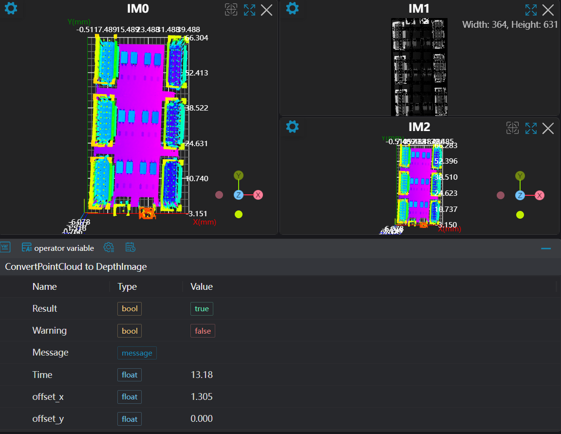
Convert the input 3D point cloud image into a 2D depth map. Map the z-value of each point to the grayscale value in the 2D depth map.
Parameter Introduction
Input Parameters

| Parameter | Range | Default Value | Description | Illustration |
|---|---|---|---|---|
| Input Image | 0-8 | 0 | The IM number for image input | |
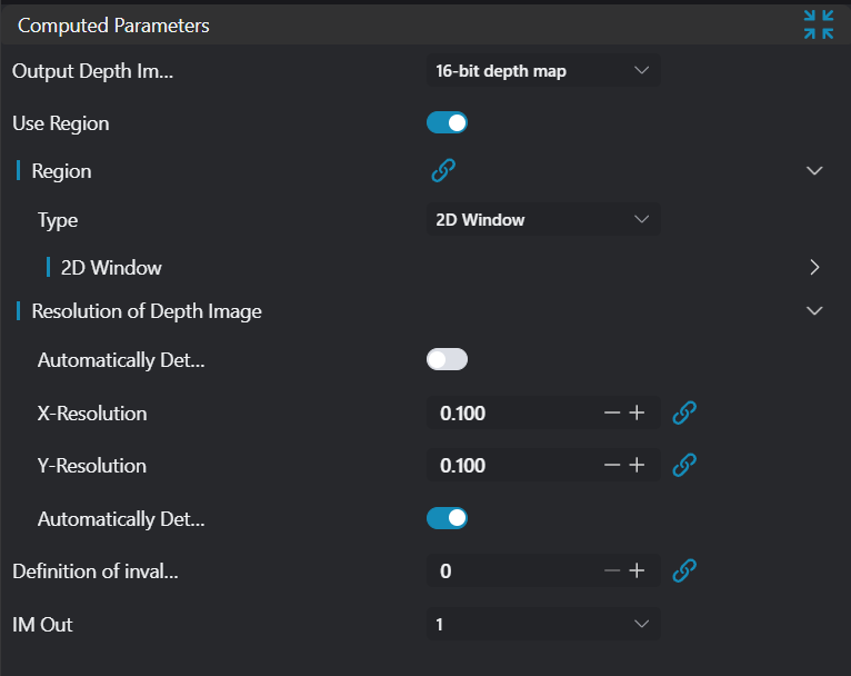
Calculation Parameters
| Parameter | Range | Default Value | Description | Illustration |
|---|---|---|---|---|
| Output Depth Map Type | Grayscale Image/Floating Point Image | Grayscale Image | Grayscale Image: Each pixel value corresponds to the normalized grayscale value of height Floating Point Image: Each pixel value corresponds to the actual height value | |
| Auto Detect Window | true/false | true | If selected, automatically calculate the point cloud range to be converted, which is the bounding box range of the point cloud image; if deselected, the Region option appears for manually setting the conversion area. | |
| Region | Only effective when Auto Detect Window is deselected, requires manual setting of the conversion region. | |||
| Interpolation | None | None | Interpolation methods not currently provided | |
| Precision | 8-bit/16-bit | 8-bit | Choose 8-bit or 16-bit. 8-bit grayscale range is [0, 255], 16-bit grayscale range is [0, 65535]. | |
| Auto Detect Z-value Range | true/false | true | If selected, automatically correspond the maximum height value in the current conversion region to black pixels, and the minimum height value to white pixels. | |
| Height Value Corresponding to Black Pixel | 0.000 | Required when Auto Detect Z-value Range is deselected. | ||
| Height Value Corresponding to White Pixel | 0.000 | Required when Auto Detect Z-value Range is deselected. | ||
| Auto Detection | true/false | true | When enabled, the input point cloud must be an ordered point cloud, and the X Resolution and Y Resolution of the point cloud will be calculated based on the row and column count of the ordered point cloud. | |
| X Resolution | 0.100 | Set the width of a single pixel in the converted depth map. The point spacing should be set as close as possible to the precision of the depth map camera's z-axis direction. Too small will cause many stripes in the image, too large will blur the image. Note: Requires manual setting when Auto Detection is turned off. | ||
| Y Resolution | 0.100 | Set the height of a single pixel in the converted depth map. The resolution should be set as close as possible to the point spacing set when the point cloud image was captured by the camera. Too small will cause many stripes in the image, too large will blur the image. Note: Requires manual setting when Auto Detection is turned off. | ||
| Output Image | 0-8 | 0 | The IM number for image output |
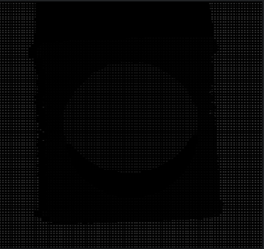
Note: In manual mode, setting the resolution too small will cause black stripes in the output depth image, as shown below. Solution: adjust the resolution to be slightly larger than the actual point spacing.
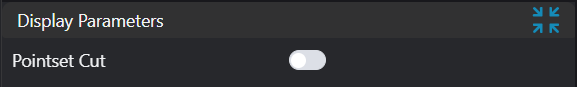
Result Display
| Parameter | Range | Default Value | Description | Illustration |
|---|---|---|---|---|
| ROI Point Set | Only effective when Auto Detect Window is deselected, displays the point set in the ROI-selected area if enabled |
Output Parameters
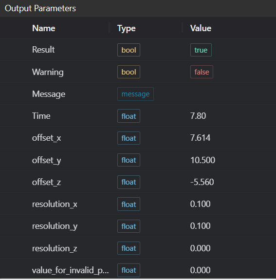
| Name | Type | Range | Description |
|---|---|---|---|
| Result | bool | true/false | true for success false for failure |
| Warning | bool | true/false | true indicates a warning false indicates none |
| Message | string | Output success, error, or warning messages. Empty if no error or warning | |
| Time | float | Operator execution time, unit: ms | |
| offset_x | float | X-axis offset | |
| offset_y | float | Y-axis offset | |
| resolution_x | float | X-axis resolution | |
| resolution_y | float | Y-axis resolution |
Mapping Relationship Between Height Value and Depth Value
| Height Value | Depth Value |
|---|---|
| Invalid point (nan) | 0 |
Height Value Corresponding to Black Pixel | 2 |
Height Value Corresponding to White Pixel | n is bit depth |
Greater than Height Value Corresponding to Black Pixel | 1 |
Less than Height Value Corresponding to White Pixel | n is bit depth |
Exception Troubleshooting
| No. | Exception Information | Corresponding Parameter | Solution |
|---|---|---|---|
| 1 | Input point cloud is empty | Check if input point cloud is empty | |
| 2 | Auto detection resolution mode requires ordered point cloud input | Auto detection resolution mode requires ordered point cloud input | |
| 3 | Input value {0} is invalid output depth map type | Output Depth Map Type | Only supports grayscale image, floating image |
| 4 | Point cloud to depth map conversion failed | Check if both xy resolutions are greater than 0 |
Example Introduction
Engineering Design
Select the
Load Point Cloudtool to load the required 3D point cloud image into IM0.Select the
Point Cloud to Depth Maptool.
Tool Usage
Select the input image for operation. The image number must match the IM number where the image is located in the project.
Select Auto Detect Window.
Set the parameters.
Check the desired display content in the Result Display section.
Click
Testto check if the image window and parameters meet expectations.If everything is correct, click
Save, then run the operator in the run list. You can view the results in the corresponding IM.