Adhesive Path Inspection - Trajectory
Operator Function
Manually select trajectory points of the adhesive path on a 2D image to measure break conditions, width, height, and edge margins of the adhesive path. Suitable for point cloud images with height transitions around the adhesive path.Before using the operator, the adhesive path point cloud needs to be adjusted to a reference planeNote: This operator requires ordered point cloud input and its corresponding 2D image (each point in the point cloud should correspond one-to-one with pixels in the 2D image)
Parameter Introduction
Input Parameters
| Parameter | Range | Default Value | Description | Illustration |
|---|---|---|---|---|
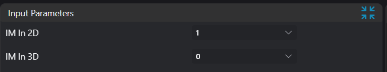
| Input Image | 0-8 | 0 | The IM number for image input | |
| Input Point Cloud | 0-8 | 1 | The IM number for point cloud input | |
Calculation Parameters
| Parameter | Range | Default Value | Description | Illustration |
|---|---|---|---|---|
| Trajectory | Point set selected by user on 2D image | |||
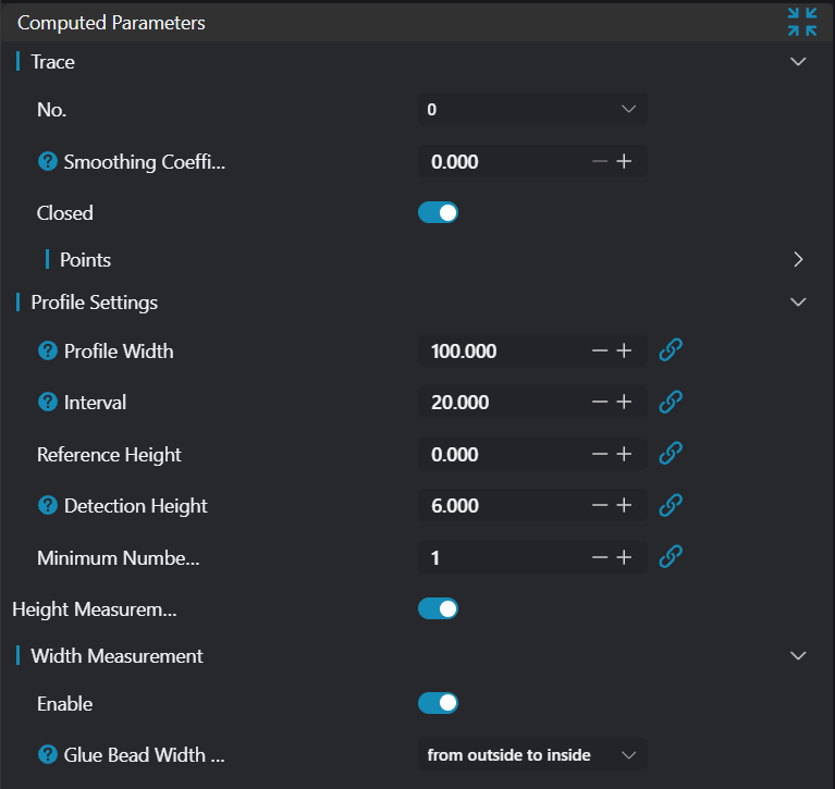
| Smoothing Factor | 0.0-1.0 | 0.0 | Smoothness of trajectory on 2D image | 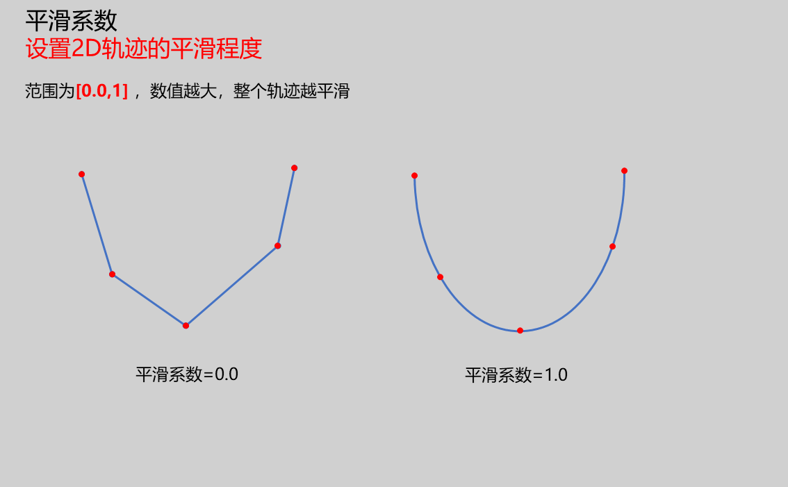 |
| Contour Width | 20.0 | Set the width for extracting contours | 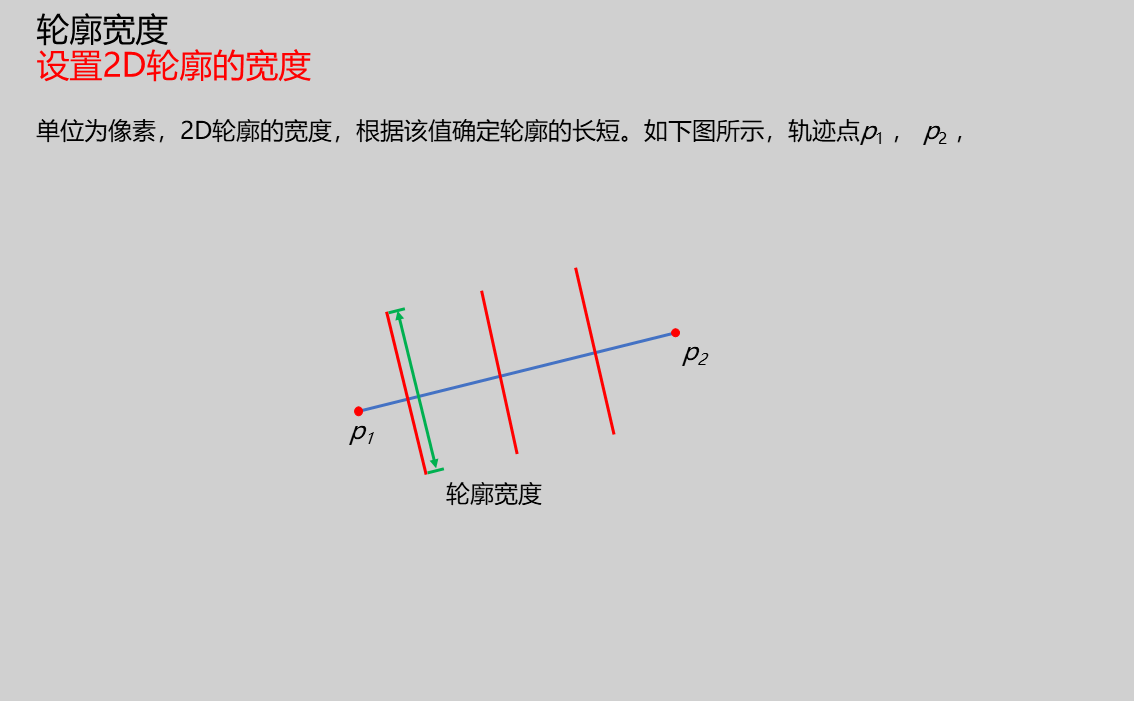 | |
| Contour Interval | 10.0 | Set the interval for extracting contours | 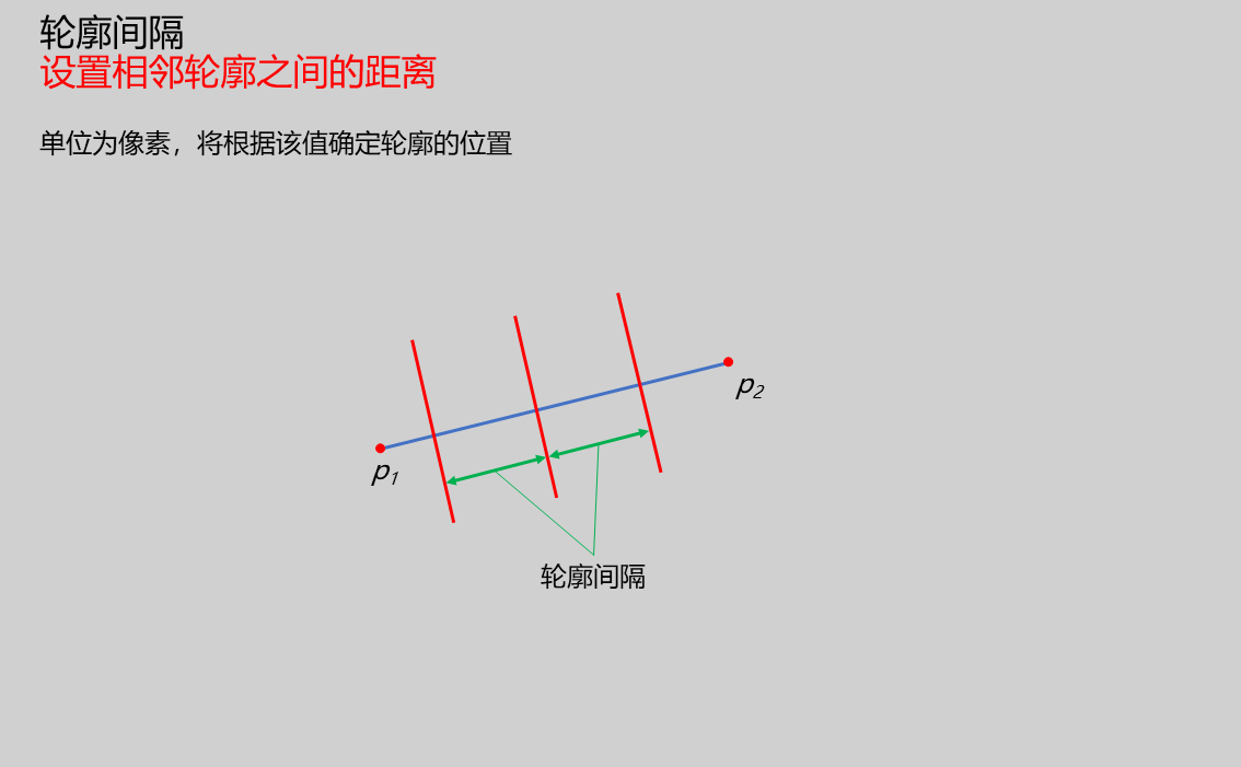 | |
| Reference Height | 0.0 | Input reference baseline for height | ||
| Detection Height | 0.0 | Input comparison height value to distinguish adhesive path | | |
| Minimum Points Above Detection Height | 10 | Set threshold for number of points in contour above detection height. If below this threshold, judged as broken adhesive | 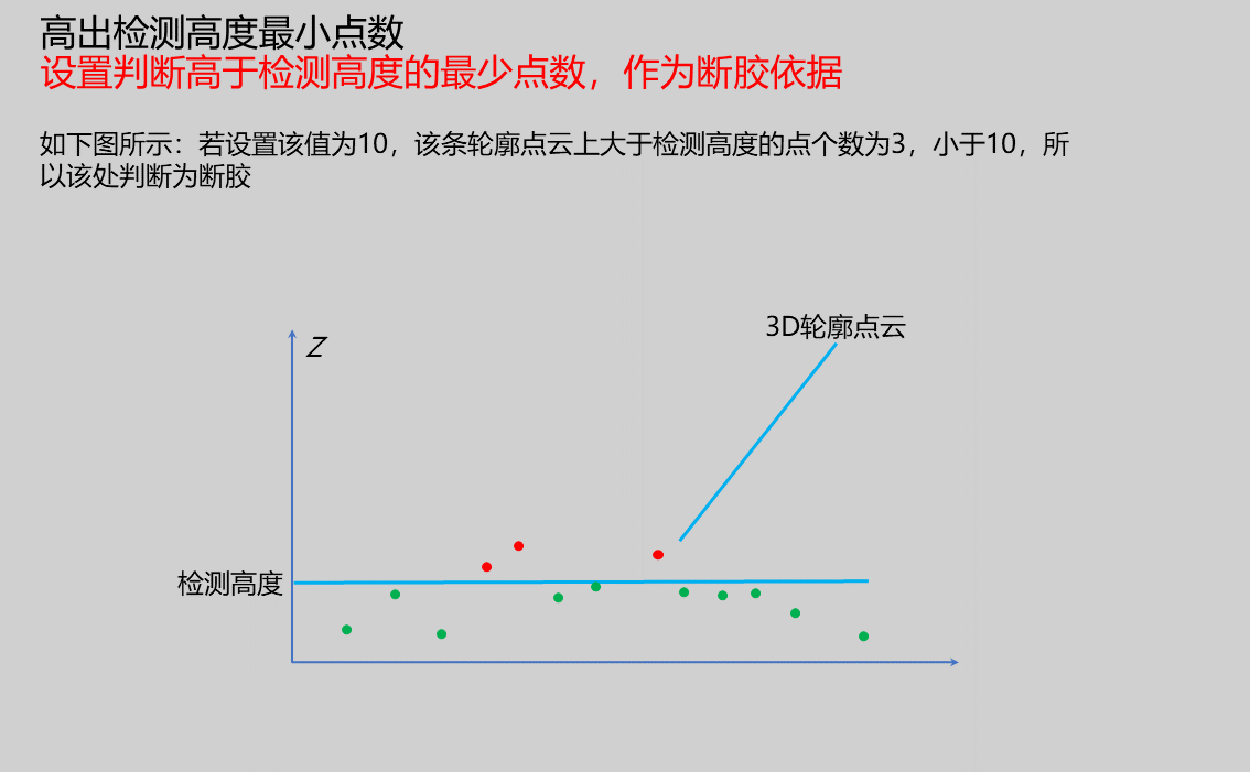 | |
| Height Measurement | true/false | false | If enabled, measure height information of adhesive path | |
| Width Measurement | When enabled, measure adhesive path width values | |||
| Width Search Mode | Inside-Out/Outside-In | Outside-In | Set mode for searching adhesive width points. When mode is Inside-Out, search from contour center point to both ends; when mode is Outside-In, search from contour start/mid point toward center | |
| Edge Margin Measurement | true/false | Only available when width measurement is enabled. Measure edge margins of contour (distance from contour start point to left width point and from contour end point to right width point) | 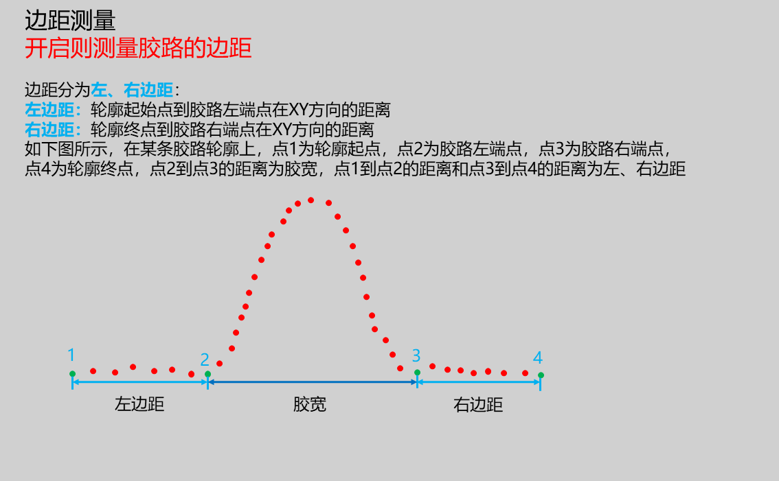 | |
| Break Result Judgment | Set parameters for judging broken adhesive | |||
| Height Result Judgment | Set parameters for judging whether height meets requirements | |||
| Width Result Judgment | Set parameters for judging whether width meets requirements | |||
| Edge Margin Result Judgment | Set parameters for judging whether edge margins meet requirements | |||
| Judgment Mode | Continuous/Any | Any | Set method for judging outliers. Set this value to n. If judgment mode is Any, then if n outliers appear in all contours, the result is judged as unqualified; if judgment mode is Continuous, then if n consecutive outliers appear in consecutive contours, the result is judged as unqualified | |
| Outlier Count | Set number of outliers. When exceeded, the result is judged as unqualified | |||
| Minimum Value | 0.1 | Set minimum value for height/width/edge margin to be judged as qualified | ||
| Maximum Value | 1.0 | Set maximum value for height/width/edge margin to be judged as qualified |
Result Display
| Parameter | Range | Default Value | Description | Illustration |
|---|---|---|---|---|
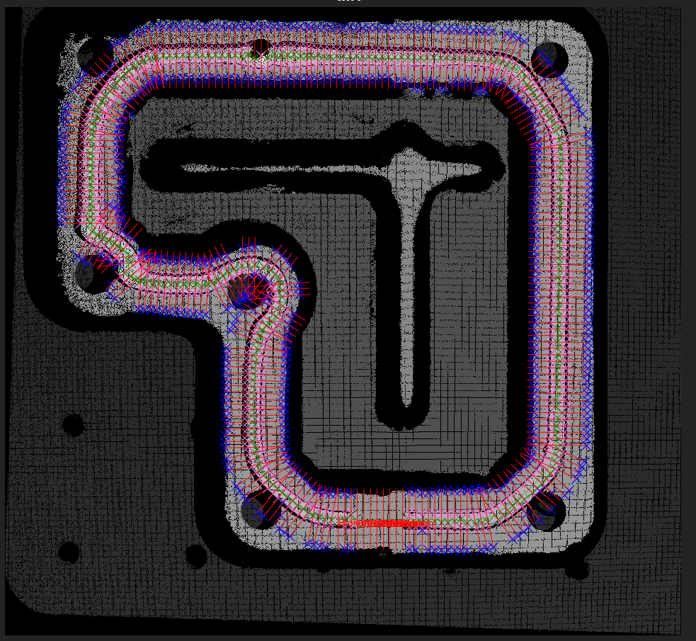
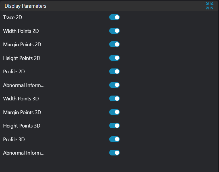
| 2D Width Points | true/false | false | Display left and right width points on 2D image (violet points) | |
| 2D Edge Margin Points | true/false | false | Display contour start points used for calculating edge margins on 2D image (valid points, blue points) | |
| 2D Height Points | true/false | false | Display height points on 2D image (green points) | |
| 2D Contour | true/false | false | Display contour lines on 2D image (red lines) | |
| 2D Break Information | true/false | false | Display break information on 2D image (red "Broken" text) | |
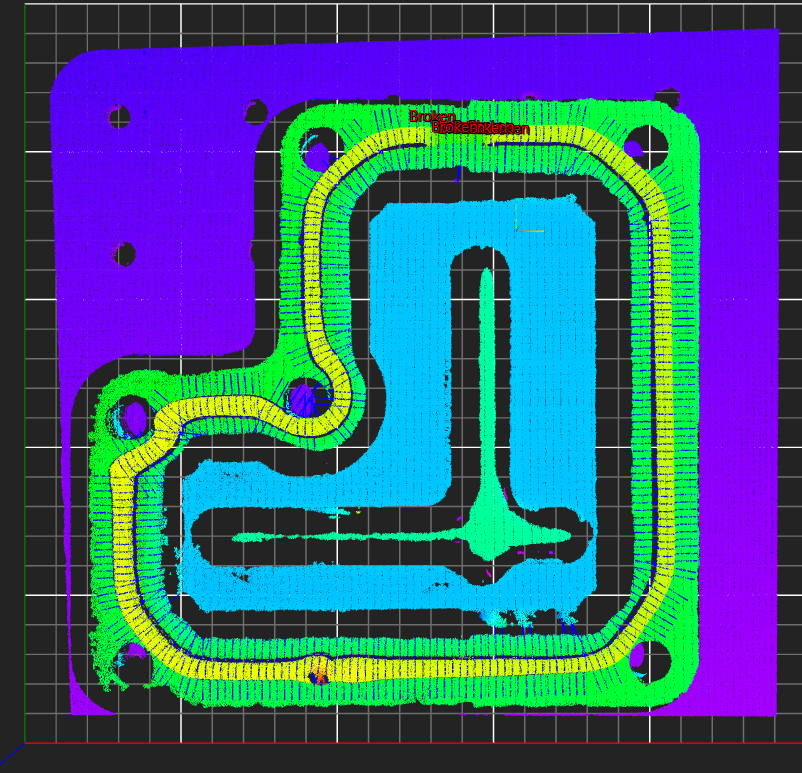
| 3D Width Points | true/false | false | Display left and right width points on 3D image (violet points) | |
| 3D Edge Margin Points | true/false | false | Display contour start points used for calculating edge margins on 3D image (valid points, blue points) | |
| 3D Height Points | true/false | false | Display height points on 3D image (green points) | |
| 3D Contour | true/false | false | Display contour lines on 3D image (red point cloud) | |
| 3D Break Information | true/false | false | Display break information on 3D image (red "Broken" text) |
Output Parameters
| Name | Type | Range | Description |
|---|---|---|---|
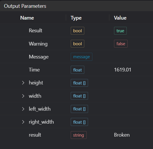
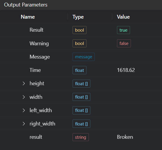
| Result | bool | true/false | true for success false for failure |
| Warning | bool | true/false | true indicates a warning false indicates none |
| Message | string | Output success, error, or warning messages. Empty if no error or warning | |
| Time | float | Operator execution time, unit: ms | |
| height | float[] | Output adhesive height | |
| width | float[] | Output adhesive width | |
| left_width | float[] | Output left edge margin | |
| right_width | float[] | Output right edge margin | |
| result | string | OK/NG/Broken | Output adhesive path inspection result |
Tip
For more detailed explanations of parameter types, please refer to Type Definitions
Exception Troubleshooting
| No. | Exception Information | Corresponding Parameter | Solution |
|---|---|---|---|
| 1 | Input image is empty | Confirm if IM contains valid 2D image | |
| 2 | Input point cloud is empty | Confirm if IM contains valid 3D image | |
| 3 | Input point cloud and input image don't match | Need to use corresponding point cloud and 2D image | |
| 4 | Input point cloud is unordered, need ordered point cloud input! | Use ordered point cloud input | |
| 5 | Input width judgment upper/lower limits invalid | Set width judgment upper limit greater than or equal to lower limit | |
| 6 | Input height judgment upper/lower limits invalid | Set height judgment upper limit greater than or equal to lower limit | |
| 7 | Input edge margin judgment upper/lower limits invalid | Set edge margin judgment upper limit greater than or equal to lower limit | |
| 8 | Input break judgment parameters invalid | Appropriately reduce outlier count | |
| 9 | Input break judgment mode is {0}, invalid break judgment mode | Break Judgment Mode | Select mode as Any/Continuous |
| 10 | Input width judgment parameters invalid | Appropriately reduce outlier count | |
| 11 | Input width judgment mode is {0}, invalid width judgment mode | Width Judgment Mode | Select mode as Any/Continuous |
| 12 | Input height judgment parameters invalid | Appropriately reduce outlier count | |
| 13 | Input height judgment mode is {0}, invalid height judgment mode | Height Judgment Mode | Select mode as Any/Continuous |
| 14 | Input edge margin judgment parameters invalid | Appropriately reduce outlier count | |
| 15 | Input edge margin judgment mode is {0}, invalid edge margin judgment mode | Edge Margin Judgment Mode | Select mode as Any/Continuous |
| 16 | Input width measurement mode is {0}, invalid width measurement mode | Width Measurement Mode | Select width measurement mode as Inside-Out/Outside-In |
| 17 | Input trajectory points {0} and {1} coincide | Trajectory Point Numbers | Change these two trajectory points so they don't coincide |
| 18 | Input trajectory point count is too low | Increase number of trajectory points | |
| 19 | Input trajectory points {0} and {1} exceed image bounds | Trajectory Point Numbers | Move these two trajectory points within image bounds |
Example Introduction
Engineering Design
Select
Load Point Cloudtool to load required 3D point cloud image into IM1;Select
Point Cloud Orderingtool to order point cloud in IM1 and save to IM1;Select
Point Cloud to Depthtool to convert point cloud in IM1 to depth map and save to IM0;Select
Adhesive Path Inspection - Trajectorytool.
Tool Usage
Select input image for operation. Image number must match IM number where image is located in project.
Set parameters.
Check desired display content in Result Display section.
Click
Testto check if image window and parameters meet expectations.If everything is correct, click
Save, then run operator in run list. View results in corresponding IM.