3D Contour Extraction
Operator Function
This operator extracts contours from the input point cloud based on user-defined cutting plane, cutting position, and cutting width. Running the operator will plot the extracted points on the image and output them to the XY plane of the input image.
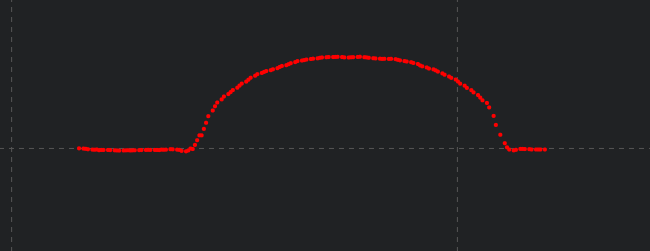
As shown in the figure, setting the cutting plane to XZ plane will plot the extracted points on the input image: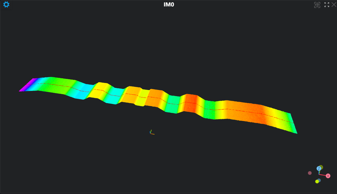 Display extracted contour points on the input image:
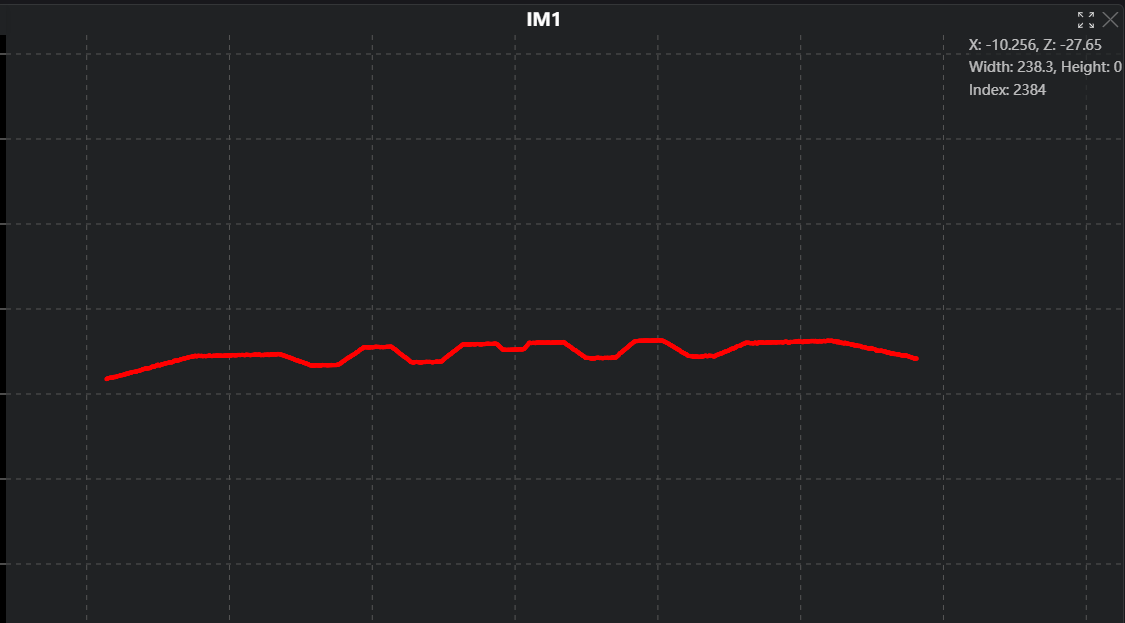
Parameter Introduction
Input Parameters

| Parameter | Range | Default Value | Description | Illustration |
|---|---|---|---|---|
| Input Image | 0-8 | 0 | The IM number for image input | |
Calculation Parameters
| Parameter | Range | Default Value | Description | Image |
|---|---|---|---|---|
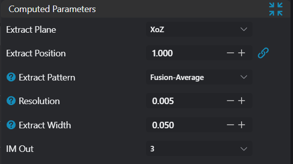
| Extraction Plane | XY Plane/XZ Plane/YZ Plane | XZ Plane | Select cutting plane; will cut the plane in this direction XY Plane: Set cutting plane as XY plane XZ Plane: Set cutting plane as XZ plane YZ Plane: Set cutting plane as YZ plane | |
| Extraction Position | 0.000 | Set cutting plane Value: Perform cutting at this value position | ||
| Extraction Mode | Nearest/Fusion-Average | Fusion-Average | These modes only support extraction planes XZ plane and YZ planeNearest: This mode only supports organized point cloud as input, will extract the contour closest to the extraction position Fusion (Average): This mode will extract points within the set extraction width, outputting contours fitted by averaging based on extraction width and resolution | 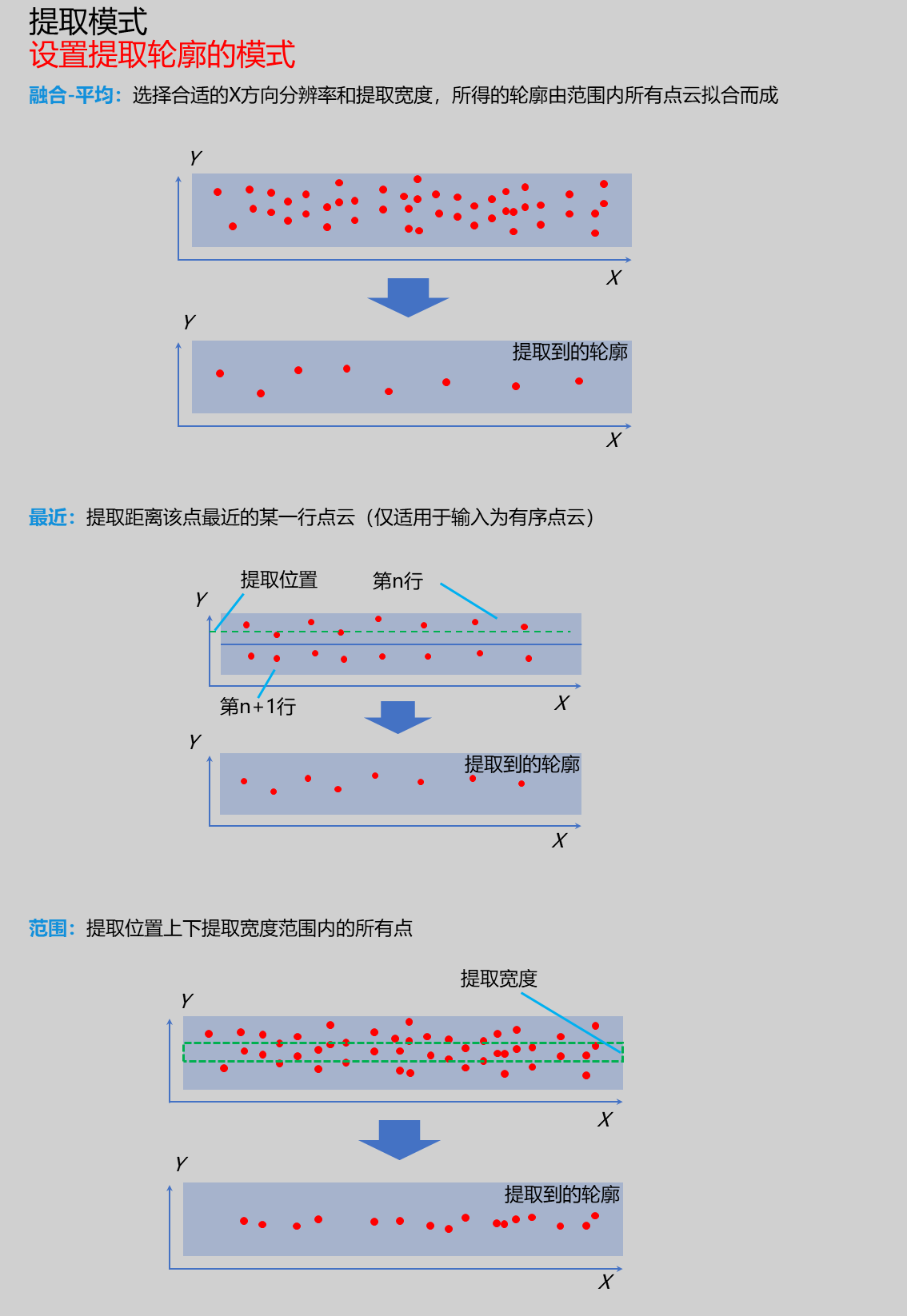 |
| Resolution | 0.100 | Enabled when extraction mode is Fusion (Average)When extraction plane is XZ plane, this resolution is the X-direction resolution of fitted contour When extraction plane is YZ plane, this resolution is the Y-direction resolution of fitted contour |  | |
| Extraction Width | 0.030 | Set cutting width value; points within the range of ± this value from the cutting position will be used as extracted contour points | 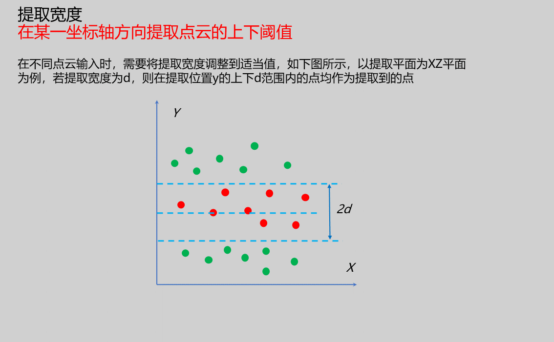 | |
| Output Image | 0-8 | 0 | The IM number for image output |
Result Display
| Parameter | Range | Default Value | Description | Illustration |
|---|---|---|---|---|
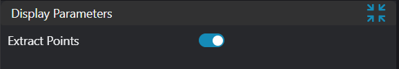
| Extracted Points | true/false | false | If enabled, display extracted points in the input image |
Output Parameters
| Name | Type | Range | Description |
|---|---|---|---|
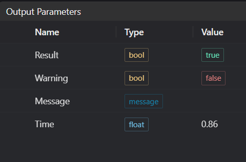
| Result | bool | true/false | true for success false for failure |
| Warning | bool | true/false | true indicates there is a warning false indicates there is none |
| Message | string | Outputs success, error, or warning information; if there is no error or warning, it is empty | |
| Time | float | Operator execution time, unit: ms |
Tip
For more detailed explanations of parameter types, please refer to Type Definitions
Exception Troubleshooting
| No. | Exception Information | Corresponding Parameter | Solution |
|---|---|---|---|
| 1 | Extracted contour is empty | None | Adjust region start and end parameters to ensure valid points exist in selected area |
| 2 | Organized point cloud required as input | None | Input using organized point cloud image |
| 3 | Input extraction mode is {0}, invalid extraction mode | Extraction Mode | Select extraction mode as Fusion-Average/Nearest |
| 4 | Input extraction plane is {0}, invalid extraction plane | Extraction Plane | Select extraction plane as XY Plane/XZ Plane/YZ Plane |
| 5 | No contour exists at input extraction position or resolution is much smaller than point spacing | None | Adjust extraction position or resolution |
| 6 | Input point cloud is empty | None | Confirm if IM contains valid points; if no valid points, load point cloud or switch to IM with valid points |
Example Introduction
Engineering Design
Select the
Load Point Cloudtool to load the 3D point cloud image to be processed into IM0;Select the
3D Contour Extractiontool
Tool Usage
Select the input image for operation; the image number must match the IM number where the image is located in the project.
Set parameters
Check the content you want to display in the result display section
Click
Testto check if the image window and parameters meet expectationsIf there are no issues, click
Save, then run the operator in the run list to view the results in the corresponding IM
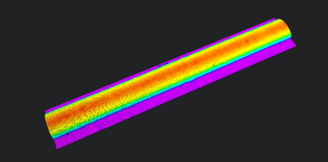
Original Image
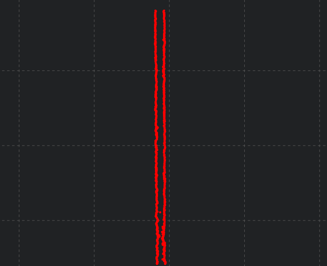
Extracted XY Plane Contour
Extracted YZ Plane Contour
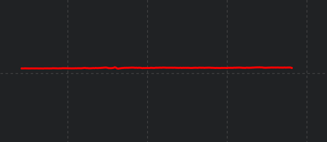
Extracted XZ Plane Contour